Hey gravity power fans, I’ve been interested for a long time in the Milkovic Secondary Oscillator and have been looking at different alternatives that could operate in a similar fashion. Experimenting on WM2D I’ve come up with an overbalanced pendulum setup that has some very interesting possibilities.
I really like the MT 143 geared levers and wondered what would happen if you mounted a pair of 143 assy’s with two 50 lb levers on top of a heavy 500 lb pendulum. Then install another pair of 143 assy’s near the 500 lb weight for counterbalancing purposes. I have installed a small motor to drive the assy’s at a continuous angular velocity, which is easily variable of course. The motor is not connected to the load except in a secondary fashion, this is similar to the Milkovic device. The motor has no intelligence in the sim as to what the 500 lb pendulum is doing. This is similar to the Milkovic design in that there is only an indirect connection between the secondary (input) and primary (output) system.
The potential OU aspect is that both pairs of 143 geared lever assy’s are all driven together off the same motor thru a pair of common chains (the green lines in the diagram) so wherever the 500 lb pendulum is located, there is no work required to rotate the 143 assy’s. We are getting the overbalancing for free minus friction of course.
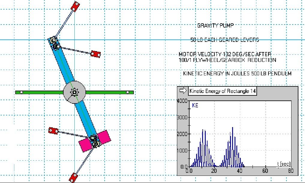
Wherever a 143 assy is ascending, the other is descending. The weighted levers in each 143 assy naturally counterbalance the other lever as long as they stay in a vertical alignment. By adding the second 143 assy we create a counterbalance for the entire secondary system, no matter the orientation or location of the main pendulum. Whatever one weighted lever is doing, there is another doing the exact opposite. What does not counterbalance is the CoG of the system. We are producing massive CoG changes nearly free.
With the Milkovic design, the input pendulum must be excited by hand at just the right time to keep the output in resonance. With this rotary analogue, a simple motor can do it with electronic controls. The motor is run at idle power, just enough to overcome the friction in the system. The motor is not under any load. There would be CF effects at higher speeds but this system is designed to operate at a very low speed, minimizing any CF buildup. The goal is massive torque here, not rpm.
There is an unknown small amount of secondary (acceleration) forces occurring that are moderated by the 200 lb flywheel rotating 100 times faster than the MT143 assy’s located at the fulcrum. So now we have all the primary forces counterbalanced out and hopefully most of the secondary forces. Most of the secondary forces should self cancel anyway as there is an equal amount of deceleration as accel.
In the graph for KE output, I have set the units in Joules because of a WM2D labeling problem with BTU’s. 1 Joule = .000948 BTU for the BTU fans out there. The following animation can be clicked on to start it.
The system is highly sensitive to the rotation speed of the motor. Just a change of 5 degrees per second in motor speed can create a huge effect on the 500 lb pendulum, driving it almost over the top from a dead stop within about 4 1/2 full swings if the right excitation speed is chosen. If a velocity of 125 deg/sec is chosen, a maximum KE of only 700 Joules is attained. Bumping it up to 132, KE jumps to 2264 Joules. This is at the resonance condition for the system.
Then once the system is up to speed, the computer controlled motor will keep the system in the sweet spot. The motor speed needs to slow down slightly once it achieves resonance. With no controls at all as in the sim, the motor then overdrives the pendulum after achieving the resonance condition and then begins actively wasting energy slowing the pendulum down until it has no energy at all!
But if we take note of the full period pendulum swing (2.7 sec) and the amount of KE increase on the last full swing (1063 joules) we get an increase of 394 joule/sec. Then since 1055 joule/sec = 1.414 hp, we can get a theoretical .53 hp continuous output if the system is maintained at resonance. And of course that does not take into account the input energy which should be small or working/air friction. The drive motor is only spinning at 35 rpm under no load other than friction so I’m wild ass guessing 125 watts which is .17 HP. So we have roughly/possibly a 3/1 potential COP. Lots of mass to generate half a horsepower but
that’s the way it is in the gravity power biz.
On an actual device one would limit the massive pendulum’s arc to maybe 270 degrees which would reduce to around 180 with a load applied, as an
arc of greater than 270 degrees wastes too much time in lateral translation. This would be done by installing a permanent magnet AC alternator at the fulcrum, which would generate output in both directions which would be then rectified to DC thru a full wave rectifier. A pair of these units side by side swinging in opposite phase would largely eliminate imbalance in the support structure. Air friction (windage) would be a very minor factor as velocities are low. The motor driving the system is located at the exact fulcrum to prevent it’s weight from reducing efficiency.
The motor driving the geared levers would be controlled for velocity by computer controlled circuitry which would keep the 500 lb pendulum in the sweet spot, or maximum resonance condition depending on load. One can observe from the KE window the sharpness of the resonance peak and that the energy quickly deteriorates when the excitation speed is not perfect. This is a job for electronic controls! A typical motion control system can control up to eight separate motors so a single control system could control 8 gravity pumps in a row. This would also divide up the computer overhead over 8 systems.
Banks of these units could be installed in a small area or even underground to create a gravity farm. It would look similar to rows of oil well pumps churning away but pumping gravity instead of oil! A 4 unit side by side pump weighing 3 tons in a backyard shed might support powering a small home (2 hp – 1500 W). A large solar or wind power setup can weigh that much. And of course, power is continuous, not dependent on erratic wind or solar conditions.
Of course a computer simulation means squat until a physical rep is done. It’s unknown at what level power could be extracted without destroying the resonance condition. However it doesn’t seem to bother the Milkovic oscillator to drive the twelve flashlights. Perhaps a program could be written in the WM2D scripting language to adjust the motor speed in the simulation to keep the system at the maximum resonance condition. That will take a bit of time. A continuous load may then be applied in both directions to simulate the AC alternator.
In a physical rep, the excitation velocity would probably change under load and the computer controlled motor could be setup to follow a lookup chart or spreadsheet that would adjust to different load and speed conditions. Or it could be controlled by simple microswitches or hall effect sensors that would simply bump the speed up or down like a thermostat or just switch the alternator load on and off to maintain the resonance condition. This would be the cheap and dirty way to go.
I have a couple of the older heavy 3 phase wheelchair motors that have very high torque but low rpm so these might be ideal to use as an AC alternator. I wired both motors together the other day thru the 3 phase, then turned one of them with a drill press motor. The second motor turned one for one with the driven motor at a very low rpm and worked bi-directionally so it looks feasible.
Now where did I leave that 500 lb pendulum? I knew I would need it for a cool project someday!
Rotary analogue to Milkovic secondary oscillator
Moderator: scott
- cloud camper
- Devotee
- Posts: 1083
- Joined: Tue Mar 15, 2011 12:20 am
That's weird.
I went back just now to
Forum Index -> General Discussion Goto page 1, 2, 3 ... 57, 58, 59 Next | View all
Then clicked on View all and scrolled down to where I quoted Cloud Camper's post of 11 August 2011 - and found it has disappeared.
Men in Black? Nah! it must be a quirk of the Bessler.com program which moves up any thread which has no replies - or does it do this to all threads?
I'll have to check with some of Alex's posts. He's always resurrecting the dead. ;-)
Last edited by Grimer on Mon Aug 19, 2013 9:36 am, edited 1 time in total.
-
- Devotee
- Posts: 1548
- Joined: Wed Oct 27, 2010 7:43 pm
re: Rotary analogue to Milkovic secondary oscillator
Hi cloud camper ,
In the last drawing in your post , the vertical setup , look at the top and bottom pair of arms , one is on the right side and one is on the left side . If you were to remove the piece in between this two sets of arms , you have a balance beam that is in balance .
Remove one of each of the pair of gears , so that you have on arm at the top and one arm on the bottom . Place the two arms on the same side of the center line , left or right . If you remove the center piece ( the vertical piece between the 2 gears ) you no longer have a balance beam as the weights is on the same side of the balance beam . Now link the two gears with a drive chain and reverse the direction ( connect left side bottom with right side top ) between the two gears so that they are in balance . Now comes the hard part to comprehend , as long as you keep the 2 arms horizontal , you have a out of balance wheel . Because the 2 weights is always in balance to each other , in any dag of rotation of the wheel , and very , very little energy is needed to keep them in that position . These 2 weights can be kept in this orientation by a pendulum , 90 dag out of phase , osculating the pair of arms 180 deg first to the one side , and on the reverse stroke back to 0 deg , as the center pivot of the weights is free rotating on a spoke of the wheel , it is obvious that the ( in the EVOLUTION drwing in the "would it be correct " thread I have drawn them as small wheels ) small wheels will rotate with the wheel and change the orientation of the weights if left unchanged , but you will end up with both arms hanging vertically down , and then you will not be able to swing them back up into balance . This is not the same as when you try to keep the arm to one side by moving it up while the wheel is turning it down , with it's own force , this cannot be done , but in this move , it can be done because the 2 weights is in balance and the pivot is free turning on the wheel axel . Say we take left hand wheel as no 1 weight . as the wheel is turning ccw , the small wheel weight will reach 6 o clock , but we want it to stay horizontal , so we need to turn the small wheel cw 90 deg at that stage , now we continiuo to 3 o clock , we have to turn it cw again 90 deg to keep it horizontal till we reach 3 , but as we pass 3 , we need to start to turn ccw , so the pendulum can oscalate and also regulate the position if the wheel is strained or free rotating . I place a drwing here for your ease .
- cloud camper
- Devotee
- Posts: 1083
- Joined: Tue Mar 15, 2011 12:20 am
re: Rotary analogue to Milkovic secondary oscillator
Looks real interesting Daano.
But I just tried to stick to the Milkovic secondary oscillator concept as much as possible.
And JB's where he said "if one weight is giving an upward impetus, another is giving an equal downward one".
I'm sure there are many variations possible on the same theme.
Just wish I had more time to spend on it. Really not too hard to build a POP and then hopefully close the loop.
The motor speed could be controlled with a simple rheostat for testing and simply do a eye-hand coordination just like the manual pendulum poking on the Milkovic mechanism. Computer controls could come later.
It does seem as though the energy is there at the resonance condition, just like the Milkovic unit driving the 12 flashlights.
We can also observe here how rising and falling weights can be used to create an energy gain, not by creating and then consuming vertical PE or CF as these are always a wash, but by creating massive Rotational PE (torque) by lateral CoG shifting.
All we're doing here is shifting the lateral CoG left and right. The combined vertical CoG for the exciter weights never changes. That means no vertical PE is ever consumed yet we're producing massive torque on the pendulum that it must respond to.
And we see how the 500 lb pendulum never reaches "punctus quietus" if we set up the motor to always maintain the resonance condition as the exciter weights are always shifting the lateral CoG faster than the pendulum can respond to it, forcing it to continually perform work trying to find the equilibrium condition. This is a case of using latency to our advantage.
We also do not violate the 1st law since the exciter weights are rotating but the vertical CoG never changes. So when the exciter weights swing, only the lateral CoG moves and then in a very linear path left and right.
Who was it that said we should use lateral thinking?
We also see weights gaining force by their own swinging.
Also, I believe a free energy generator should be capable of destroying energy as well as creating it, and this mechanism does exactly that halfway between the resonance peaks at the low points on the KE graph.
Daano, could you please go ahead and simulate your idea in WM2D? I have some difficulty in following your description.
Thanks buddy!
re: Rotary analogue to Milkovic secondary oscillator
CC .. here is a sim built by a friend of mine [Tin_head] 10 years ago - he called it the T-Bar Oscillator.
I thought it might have some interest for you as like your Oscillator & Milkovic's it appears to only need a small input of pulse energy to keep resonance - the idea was to have a forced feedback between the Counter Weight & the horizontally extended masses so that CoG moves quite a distance laterally but not much vertically.
- Attachments
-
- tbar_021.wm2d
- T-Bar Oscillator
- (37.51 KiB) Downloaded 371 times
-
- Devotee
- Posts: 1548
- Joined: Wed Oct 27, 2010 7:43 pm
re: Rotary analogue to Milkovic secondary oscillator
Hi cloud camper ,
I do not own a sim program , I cannot do what you ask , sorry .
re: Rotary analogue to Milkovic secondary oscillator
Suggestion: Download the demo version - you can't save however.
Build the device you want to test - take a screen shot & post it here - it saves an enormous amount of work for someone who might then build what you've shown.
- cloud camper
- Devotee
- Posts: 1083
- Joined: Tue Mar 15, 2011 12:20 am
re: Rotary analogue to Milkovic secondary oscillator
Thanks for that Fletcher.
I downloaded it and am running it now.
There doesn't seem to be a lot of pendulum movement. I think because the
weights are acting on a very short lever arm.
I tried for weeks to get the most pendulum movement but I could never find a combo that would drive it completely over the top.
But we can get it nearly there in about 4 1/2 full swings. Not too bad lifting 500 lbs 5 feet vertically in 10 seconds for essentially no work input. At startup we would have to accelerate the exciter weights to the resonant excitation speed so that would entail some work but once at resonance, almost nothing.
Just a few changes required from here to get to JB's wheel, namely adding impacts and weight swapping.
With this (pendulum) design, we are creating overbalancing on both sides of the "wheel" as it never does a full rotation. With full rotation, we only need the OOB on one side of the wheel. This is because a wheel only goes down on one side (duh).
We can observe from this mechanism that we have an alternating imbalance which switches from side to side. This is the same imbalance we need for full rotation except we need it only on one side of the wheel and needs to alternate from balance to imbalance. This provides a dynamic imbalance mechanism that the wheel can then respond to just like our pendulum.
The wheel cannot be constantly out of balance as this creates a static (non changing) gradient. A dynamic response from the wheel (rotation) requires a dynamically changing gradient. This is why the balance must alternate from balanced to imbalanced then back again.
Otherwise the wheel "catches up" to the input and stops as it has found "punctus quietus".
@Daano - I'm getting into your idea now and may have some questions for you. Thanks for your idea.
It would really be swell if you could get up to speed on WM2D. You have so many good ideas I don't see how you can do it without simulating.
And it makes it so much easier for others to understand your concept.