I am guessing that Wolff thought he heard a spring unwinding. Probably the spring made a distinct noise as opposed to a swinging lever, like a "twangy" sound?Robinhood46 wrote: ↑Mon Jul 24, 2023 4:36 pm I have difficulty understanding how he distinguished between Bessler pushing down on a spring and pushing down on a lever that has a counter weight. Both, if released, would give the same noise when they seek their initial position.
Part Three is the Charm
Moderator: scott
Re: Part Three is the Charm
Re: Part Three is the Charm
In an earlier post I discussed MT36. I believed B. included the distant view of the figure to hint at the attachment of the weight-lever to a parallelogram as viewed from the drum side. Now I was to discuss MT16 which I believe is a hint of how the grindstone of a runner wheel appears as viewed from the rim side. Here are the notes of MT16:
"No. 16 This model shows how the weights are connected and how they raise the internal spheres at A up and around. The accompanying special figure shows how the edge of the wheel appears at the tensions when it is opened." MT Collins
The side view or "special figure" shows a series of squarish shapes sandwiched between the dark drum frames. See red selection of the upload. B.'s inclusion of the figure is superfluous (to me) as it does not reveal anything meaningful in and of itself. So why did he bother? Again like MT36 I feel he was hinting (even more cryptically) the superficial appearance, the semblance, of a runner's grindstone when seen from the rim. Compare this to the nested parallelograms of my wheel and the rim view does show the parallelograms resembling squarish shapes as well. Hmm ...
B. was a very visually oriented person. Reading the metaphors of the AP prose one can see this. I would posit that he left certain hints by way of semblance in drawings even though the source of such semblance is of a different nature. An analogy to this is the extinct Tasmanian tiger. Visually its physical form could be mistaken for a canine but it is in fact a marsupial.
Select Quotes:
"The motive force, the ability to move itself and drive other objects makes up the FORM of the device .. the essence. As an example of the ideas I am discussing, consider the case of two small metal spheres, one of iron and one of lead. For both of them, their FORM consists in their regular sphericity. But we find that placed in a furnace, one loses its shape quicker than the other. Therefore the greater or lesser "meltability" of such spheres is not the result of "sphericalness" - common to both - but of the physical characteristics of the two materials. And it is this "material accident" which is the FORMAL CAUSE of the difference." DT 221 Collins
"The case is no different from that of a leaden or even waxen sphere. They are both as perfectly deserving of the description "sphere" as is an iron one, despite the fact that the latter [iron] will withstand fire and other attacks better than the two former [lead & wax]. For form gives the essence of the thing." DT 222 Collins
- Attachments
-

Re: Part Three is the Charm
John Collins MT 2007 Hard Copy .. No. 16 This model shows how the weights are connected together and how, at the same time, they pull the internal spheres at A up and around. The accompanying special figure shows how the rim of the wheel has some openings for the pullers. ... underlining to identify the main differences .."No. 16 This model shows how the weights are connected and how they raise the internal spheres at A up and around. The accompanying special figure shows how the edge of the wheel appears at the tensions when it is opened." MT Collins
Re: Part Three is the Charm
Thanks. Neither translation invalidates my opinion of the superfluity of the figure's inclusion in the drawing. It is plainly obvious looking at the wheel itself that there are apertures at the base of the levers. How could the tensions pass through the rim at that spot if for not? So I maintain the figure's presence was unnecessary. I feel B. added it to allude to something else, and it's curious to me that the openings are squares instead of circles, ovals, etc.Fletcher wrote: ↑Mon Jul 31, 2023 1:59 amJohn Collins MT 2007 Hard Copy .. No. 16 This model shows how the weights are connected together and how, at the same time, they pull the internal spheres at A up and around. The accompanying special figure shows how the rim of the wheel has some openings for the pullers. ... underlining to identify the main differences .."No. 16 This model shows how the weights are connected and how they raise the internal spheres at A up and around. The accompanying special figure shows how the edge of the wheel appears at the tensions when it is opened." MT Collins
-
johannesbender
- Addict

- Posts: 2544
- Joined: Thu Apr 18, 2013 3:29 pm
- Location: not important
Re: Part Three is the Charm
And at the left of A and the wheel they all pulled down together , just a good example of a design during the time he was gullable delusional and uneducated , luckily everyone was warned that nothing of a pm could be learned from them as designed.Fletcher wrote: ↑Mon Jul 31, 2023 1:59 amJohn Collins MT 2007 Hard Copy .. No. 16 This model shows how the weights are connected together and how, at the same time, they pull the internal spheres at A up and around. The accompanying special figure shows how the rim of the wheel has some openings for the pullers. ... underlining to identify the main differences .."No. 16 This model shows how the weights are connected and how they raise the internal spheres at A up and around. The accompanying special figure shows how the edge of the wheel appears at the tensions when it is opened." MT Collins
Its all relative.
Re: Part Three is the Charm
I want to discuss MT25. This is what B. says in the teaser:
"No. 25 This is the previous model except for some differences. It is sketched with longer poles. There is something
misleading about the diagram, for the poles, when coming out, must not project so far out but must bend somewhat further inwardly. There is more to it than one supposes; one must study the diagram extensively."
B. states that the poles are drawn incorrectly showing excessive outward movement but at the same implies that such movement shouldn't be disregarded. I believe he is hinting at second set of poles projecting away from the axle. Coupled to the poles already shown in the figure they form a quadrilateral, like a stork's bill unit ...
Stay tuned for I have another (and hopefully final) insight on the Toys Page ...
- Attachments
-
Re: Part Three is the Charm
For comparison ..
2007 MT Hard Copy .. No. 25. This is similar to the previous model except that it is drawn somewhat differently and with longer rods; there is something misleading about the diagram, because the folding rods should not project so far out but must bend further inward. There is more to this than one might think. Mark my words.
Re: Part Three is the Charm
My 2 cents mryy .. what's my/our takeaways from the MT25 comments ?? .. there is some solid bankable information .. the poles should not project so far outwards (correct) ..mryy wrote:I want to discuss MT25. This is what B. says in the teaser:
"No. 25 This is the previous model except for some differences. It is sketched with longer poles. There is something
misleading about the diagram, for the poles, when coming out, must not project so far out but must bend somewhat further inwardly. There is more to it than one supposes; one must study the diagram extensively."
2007 MT Hard Copy .. No. 25. This is similar to the previous model except that it is drawn somewhat differently and with longer rods; there is something misleading about the diagram, because the folding rods should not project so far out but must bend further inward. There is more to this than one might think. Mark my words.
B. states that the poles are drawn incorrectly showing excessive outward movement ( ....... ) but at the same implies that such movement shouldn't be disregarded.
I believe he is hinting at second set of poles projecting away from the axle. Coupled to the poles already shown in the figure they form a quadrilateral, like a stork's bill unit ...
Stay tuned for I have another (and hopefully final) insight on the Toys Page ...
And then there are possible associations/speculations to be drawn from context, but not bankable imo - i.e. your referring to the "more to it/this than one might think/suppose" associated with implying that such movement shouldn't be disregarded - the context flow suggests a link to the former sentences but is this a reliable (safe) or logical assumption where B. is concerned ? .. what we can infer imo is that a mechanical movement is procured that has relevance to his final solution (but not necessarily the same format as that movement), imo .. just that one is required ..
What is bankable about MT25 ? ..
It can't and won't ever work as a self-moving (PM) wheel - fact !
It employs a pivoted falling weighted-lever, pivot connected to the hinged poles to cause the poles and hinge joint to accelerate/move outwards .. iow's, the lw loses PE and gives the poles and hinge joint KE in equal measure (not counting losses) ..
The hinge joint of the poles runs a rope connection to the opposite sector lever-weight (lw) et al - this rope connection is completely redundant, as shown, because the lower sector lw would move downwards towards 6 o'cl of its own volition, and does not need nor require the rope pull-along connection as is suggested in the diagram (same for MT24) .. therefore, the rope pull connection is something to be contemplated as essential in another mechanical context imo ..
IOW's, something (possibly lw-like) falls under gravity and loses PE, which in turn, thru rope pull connection, influences another object to gain speed and KE, imo !
In short, a mechanical push and pull of forces theme repeated in the Toy's Page ..
Last edited by Fletcher on Fri Aug 04, 2023 1:21 am, edited 1 time in total.
Re: Part Three is the Charm
See upload of MT24 & 25 and B.'s accompanying notes. I maintain that B. was addressing the hinged poles and the extent and direction of their movement around their hinge joint. These poles exhibit elements/semblance of the Stork's Bill (SB) about which B. made positive statements throughout MT. If the Toys Page is any indication a runner wheel will contain a form of the SB. It is reasonable to me that B. was dropping hints in MT 24 & 25 regarding its application.Fletcher wrote: ↑Fri Aug 04, 2023 12:10 am My 2 cents mryy .. what's my/our takeaways from the MT25 comments ?? .. there is some solid bankable information .. the poles should not project so far outwards (correct) ..
And then there are possible associations/speculations to be drawn from context, but not bankable imo - i.e. your referring to the "more to it/this than one might think/suppose" associated with implying that such movement shouldn't be disregarded - the context flow suggests a link to the former sentences but is this a reliable (safe) or logical assumption where B. is concerned ? .. what we can infer imo is that a mechanical movement is procured that has relevance to his final solution (but not necessarily the same format as that movement), imo .. just that one is required ..
The lower sector lw swings down to 6:00 due to gravity which causes the connecting rope to pull the opposite sector poles inward and achieve overbalance. I don't think the diagram ever suggested that the rope was the source of the lw moving toward 6:00.What is bankable about MT25 ? ..
It can't and won't ever work as a self-moving (PM) wheel - fact !
It employs a pivoted falling weighted-lever, pivot connected to the hinged poles to cause the poles and hinge joint to accelerate/move outwards .. iow's, the lw loses PE and gives the poles and hinge joint KE in equal measure (not counting losses) ..
The hinge joint of the poles runs a rope connection to the opposite sector lever-weight (lw) et al - this rope connection is completely redundant, as shown, because the lower sector lw would move downwards towards 6 o'cl of its own volition, and does not need nor require the rope pull-along connection as is suggested in the diagram (same for MT24) .. therefore, the rope pull connection is something to be contemplated as essential in another mechanical context imo ..
IOW's, something (possibly lw-like) falls under gravity and loses PE, which in turn, thru rope pull connection, influences another object to gain speed and KE, imo !
If you are referring to the hammermen pantographs C & D there may be a push-pull action. To me they're simply moving in opposite directions.In short, a mechanical push and pull of forces theme repeated in the Toy's Page ..
Re: Part Three is the Charm
At face value your deductions and associations would seem plausible and reasonably made .. I however suggest that B.s was offering understanding at a layer or two below that .. undoubtedly in my mind also the final mechanical solution contains a SB application ..mryy wrote:See upload of MT24 & 25 and B.'s accompanying notes. I maintain that B. was addressing the hinged poles and the extent and direction of their movement around their hinge joint. These poles exhibit elements/semblance of the Stork's Bill (SB) about which B. made positive statements throughout MT. If the Toys Page is any indication a runner wheel will contain a form of the SB. It is reasonable to me that B. was dropping hints in MT 24 & 25 regarding its application.
I've read you comment above a couple of times and I just don't comprehend what you are saying there .. when I get time I'll knock up a quick sim of MT25's main parts and characteristics as I see it and we can compare notes ..mryy wrote:The lower sector lw swings down to 6:00 due to gravity which causes the connecting rope to pull the opposite sector poles inward and achieve overbalance. I don't think the diagram ever suggested that the rope was the source of the lw moving toward 6:00.
That's one interpretation ..mryy wrote:If you are referring to the hammermen pantographs C & D there may be a push-pull action. To me they're simply moving in opposite directions.
No. 24 This invention ought not to be scorned. It consists of separate levers with weights. Between the weights are small iron poles with hinges. The poles fall inward when the levers close. There is something one must learn first before one can grasp and correctly understand the good quality of the invention.
2007 MT Hard Copy .. No. 24. This invention should not to be scorned. It consists of special weighted levers and some hinged iron rods that close between the levers and can fold inward. There is, however, more to explain about it before you will grasp and correctly understand its good qualities.
Last edited by Fletcher on Fri Aug 04, 2023 11:44 pm, edited 1 time in total.

[ Pornographic Trig-eometry! ]
.
.
click here for legible graphics
.
https://besslerwheel.com/forum/download ... &mode=view
.
.
click here for legible graphics
.
https://besslerwheel.com/forum/download ... &mode=view
.
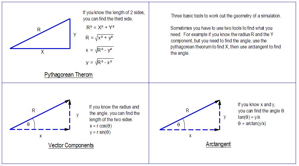
Wubbly wrote: ↑Sun Aug 25, 2019 9:21 pm When I work out the point geometry for the simulations, I find myself using 3 basic tools over and over again.
Pythagorean threrum
Vector Components
Arctangent
Depending on what variables you know, sometimes you have to use two tools to find what you need.
WM2D doesn't give you an arcsine or arccosine function, but usually arctangent is good enough. Only on MT24 and MT25 I wished I had an arccosine or arcsine function to use in conjunction with the law of sines or the law of cosines, but usually everything can be broken down into right triangles.
Last edited by WaltzCee on Sat Aug 05, 2023 1:38 am, edited 1 time in total.
........................¯\_(ツ)_/¯
¯\_(ツ)_/¯ the future is here ¯\_(ツ)_/¯
Advocate of God Almighty, maker of heaven and earth and redeemer of my soul.
Walter Clarkson
© 2023 Walter W. Clarkson, LLC
All rights reserved. Do not even quote me w/o my expressed written consent.
¯\_(ツ)_/¯ the future is here ¯\_(ツ)_/¯
Advocate of God Almighty, maker of heaven and earth and redeemer of my soul.
Walter Clarkson
© 2023 Walter W. Clarkson, LLC
All rights reserved. Do not even quote me w/o my expressed written consent.
Re: Part Three is the Charm
Some of B.'s clues are about associations, about superficial appearances ... about semblances. Remember my earlier example of the Tasmanian tiger. It may look like a canine but it really is a marsupial. IOW things are not what they appear ... Your interpretation of the MT24 & 25 is more or less in line with the diagrams' theory of operation -- push/pull via rope. My interpretation takes a departure from that. I look at their visuals *only* and attempt to reconstruct a different mechanism that can arrive at a similar if not the same visual. I feel that is what B. meant in the Toys Page when he asks the reader to apply the 5 games in a different way -- different mechanisms if you will that can re-create the same or similar image (static or kinetic) as those games. B. wasn't going to give away his hard-earned secret so easily, right?At face value your deductions and associations would seem plausible and reasonably made .. I however suggest that B.s was offering understanding at a layer or two below that .. undoubtedly in my mind also the final mechanical solution contains a SB application ..
I was responding to this statement of yours:I've read you comment above a couple of times and I just don't comprehend what you are saying there .. when I get time I'll knock up a quick sim of MT25's main parts and characteristics as I see it and we can compare notes ..
"The hinge joint of the poles runs a rope connection to the opposite sector lever-weight (lw) et al - this rope connection is completely redundant, as shown, because the lower sector lw would move downwards towards 6 o'cl of its own volition, and does not need nor require the rope pull-along connection as is suggested in the diagram (same for MT24)"
I see what you are saying now. When you used the phrase "lower sector lw" I initially thought you meant the lower right quadrant of the wheel when it was about the lower left quadrant. And B. was aware of that. He added ropes to the figures in an attempt to hasten the overbalancing. Still they are in the MT collection.
-
Sam Peppiatt
- Devotee

- Posts: 1897
- Joined: Tue Dec 01, 2015 4:12 pm
Re: Part Three is the Charm
Fletcher,
I think you are right about the storks bills, for several reasons. They can change the normal arc motion of a lever, to straight line motion and, multiply the distance moved many times. Also, they automatically reverse the direction of motion every half turn of the wheel. I.,E., in on the up side and out on the down side. Finally, they can easily be driven with a heavy disc.
Two or three stages,(of a storks bill), can increase the diameter of a wheel several times. Maybe this helps to explain why Bessler's wheel(s), were so thin yet so large in diameter------------------------Sam
Re: Part Three is the Charm
Actually .. I think both our interpretations are strategically aligned .. a visual cue of an important action .. and because he didn't want his secret exposed early or easily (no MT is a blue-print), it is up to us to work out the correct context and application of the principles employed in MT25 in conjunction with the Toy's Page symbolisms - of that general direction we are in complete agreement !mryy wrote:
... Your interpretation of the MT24 & 25 is more or less in line with the diagrams' theory of operation -- push/pull via rope. My interpretation takes a departure from that. I look at their visuals *only* and attempt to reconstruct a different mechanism that can arrive at a similar if not the same visual.
I feel that is what B. meant in the Toys Page when he asks the reader to apply the 5 games in a different way -- different mechanisms if you will that can re-create the same or similar image (static or kinetic) as those games. B. wasn't going to give away his hard-earned secret so easily, right?
For those interested .. I said yesterday I would build a quick sim of MT25 in operation and animate it .. why reinvent the wheel ? - this morning I went back and found Wubbly's excellent studies of MT25 and adapted his wm2d file for our purposes instead ..
n.b.1 My wm2d file is attached for download below .. the sim is built with "slider" inputs to the left of screen - this means these inputs can be changed while the sim is running (on the fly so to speak) .. I slide adjust the green rope length initially, then give the red hinge an equal mass (kgs) to the yellow lever-weight .. all the time the wheel is being turned by a motor - then lastly I turn the motor drive OFF to see what happens ..
You can follow these inputs and results by watching the animation I made below - note where the System COM is located as these changes take place etc .. fwiw the lower sector lw moves towards the 6 o'cl position and is slowed down when mass is given to the hinge, but this makes the System COM even worse IINM ..
n.b.2 the rods have to be more inward else the yellow lever-weight will bounce upwards and the rods project outwards - this makes them fold the wrong way (not inwards) when it is time to close them in the lower opposite sector (not sim tested but anticipated) ..
n.b.3 sorry for the quickness of the animation - the program I use only allows a limited time and memory for capture before it just stops recording, so I have to not be tardy and trust you can watch it a few times to figure out whats happening ..
................

................
- Attachments
-
- Wub-MT25-1a.wm2d
- Wubbly MT25 Adapted ..
- (32.56 KiB) Downloaded 96 times
Last edited by Fletcher on Sun Aug 06, 2023 12:49 am, edited 2 times in total.