Part Three is the Charm

A Bessler, gravity, free-energy free-for-all. Registered users can upload files, conduct polls, and more...

Moderator: scott

Post Reply
johannesbender
Addict
Addict
Posts: 2547
Joined: Thu Apr 18, 2013 3:29 pm
Location: not important

Re: Part Three is the Charm

Post by johannesbender »

Fletcher wrote: Sat Aug 12, 2023 11:25 pm And to round out further the theme of Off-Set Split Axles here are some RB's I made .. note that I actually built a mock-up of the Off-Set Chain addition a few years ago (additional to my Ramelli geared design with Off-Set Chain addition of another thread) to see if point loading had any effect - Answer .. NO !

No turny spinny .. N.B. I'd still like to sim the vproject1 V split axles (cranked in the same plane) wheel - the real-world build 20 years ago had no torque either IIRC .. sims attached ..
To answer in full i would have to also include the RB , as you know a lever can be applied differently and the same case is true for any other mechanical implement even the RB , therefor i would comment on the specific use case of the RB demonstrated in both the sims shown.

Sim1: Any position a mass occupies along the arms , on any of the arms ,attached to the wheels which are the same distance from the center to each arm everywhere,
produces the same force and losses the same PE and results in the same KE .
The amount of PE and KE and force for the masses on the arms is also equal to a mass connected at the same radius from the center to the arm connection on a normal wheel and also a lever.

In fact the masses move along the same radius at the same velocities , the center of gravity is actually completely irrelevant , the distances from the center to the arms and the force each mass applies to the arms are the factors that matter.

A nice way to make a simple and perfect RB on the computer ,is to motor/turn the arms in the opposite direction of the wheel with the same rpm as the wheel ;)
Last edited by johannesbender on Sun Aug 13, 2023 4:55 pm, edited 2 times in total.
Its all relative.
UbWe
Aficionado
Aficionado
Posts: 410
Joined: Wed Jul 05, 2023 2:22 am

Re: Part Three is the Charm

Post by UbWe »

A variation of a previous build. Being attacked for being disabled caused me to miss it. After all, some people have to tolerate
their families. And since I basically learned to talk in Norway I will never be liked in an English speaking country, This is actually
moving the retraction disc on a FAILED build. I am such a loser. There's no way something that develops so little torque could
ever work. After all, if it could've worked then it would've been built and working by now. Some of us are just losers and deserve
being treated like we are a waste of life.

There is a Montana farmer who I told I will see about reinventing sustainable farming so if it would help her family farm then I'll
help them. No reason why Montana farmers should have to suffer being treated like me. That requires me to be right about
science. Otherwise it's "aren't Montana farmers Canadian?".

This is a failed build and explains why I have to quit building because this is a failed build. https://www.youtube.com/watch?v=s26HbfwDFz8
That's the only thing that matters. After all, do I have working wheel? I don't. So I have to quit building. This means I won't have surgery either.
It's a d@mn shame perpetual motion is impossible. At least this way people won't be offended by my pursuing Bessler's Wheel or perpetual motion in
this forum. There is a Plan C. I just won't bother with having another surgery.

p.s., That video is from 1 year ago. Moving the retraction disc can't make it more efficient because it's a failed build.
Attachments
R3.png
Last edited by UbWe on Sun Aug 13, 2023 10:50 pm, edited 4 times in total.
User avatar
JUBAT
Aficionado
Aficionado
Posts: 879
Joined: Fri Feb 17, 2023 6:42 pm

Re: Part Three is the Charm

Post by JUBAT »

Nobody around here is attacking you for being disabled. In fact in another thread and at least a couple times I've personally encouraged you check in with the V.A. so you can get help with your surgical issue. I've also encouraged you to build and share.

As I asked in the other thread, is it really and truly that hard to just act a decent human being, enjoy building and sharing, without all the other bullshit? Really?
neuberlintourist1
Enthusiast
Enthusiast
Posts: 62
Joined: Thu Oct 14, 2021 10:38 am

Re: Part Three is the Charm

Post by neuberlintourist1 »

mryy wrote: Mon Aug 07, 2023 5:12 pm besslerw71.jpgFor structural stability I added a second cross-rod to the corner of the stork's bill unit facing the wheel rim. See diagram legend on left. This will not obstruct the movement of the blade spring on the ascending side.
Image

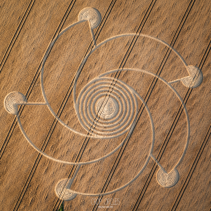
Your conccept on start looked like aa very new cropcircle-http://cropcircleconnector.com/2023/com ... 2023a.html
Attachments
besslerw71.jpg
besslerw71.jpg (34.05 KiB) Viewed 45669 times
Last edited by neuberlintourist1 on Mon Aug 14, 2023 4:22 am, edited 2 times in total.
mryy
Enthusiast
Enthusiast
Posts: 246
Joined: Sat Nov 26, 2022 3:08 pm

Re: Part Three is the Charm

Post by mryy »

neuberlintourist1 wrote: Mon Aug 14, 2023 4:21 am Your conccept on start looked like aa very new cropcircle-http://cropcircleconnector.com/2023/com ... 2023a.html
Crop circle makers maybe reading the BW Forum? It looks to be a 5-arm spiral shape superimposed over a 5-radii star with circles at end. Cool.
mryy
Enthusiast
Enthusiast
Posts: 246
Joined: Sat Nov 26, 2022 3:08 pm

Re: Part Three is the Charm

Post by mryy »

MT17Disc.jpg
I want to discuss MT17.

Let's start with the lever-like figure drawn above the wheel diagram (see red selection). I am guessing it either represents the eight weight-levers' front profiles (how they look when viewed from the rim of the wheel). Or, it represents the side profile of the springs (the circles) to which the weight-levers are attached closely around the axle. In that case the springs are arranged along the z-axis , i.e. in and out of the diagram page.

This lever has a tapered form as one can see. Let's assume it represents a spring. Is it possible that B. is hinting of an optimal shape where the spring must be widest at its base and narrowest at the tip? Could this form advantageously affect the way the spring unwinds on the ascending side of the turning wheel? That is, when the tapered spring releases its potential energy the weight near the bottom of the wheel is lifted upward "in a flash" as B. puts it. We can also observe this tapered form in the stork's bill (SB) drawn on the left side of the Toys Page, and the SB conveys an upward direction too. Is this a coincidence? I did say many, many days ago that items in the Toys Page can carry multiple meanings.

Now look at the three levers congregating on the lower section of the wheel (see blue selection). They appear to "hang together" for a time just before being lifted. It seems to me that B. was hinting of a phenomenon in a runner wheel where multiple levers momentarily appear in close proximity to each other (around the bottom region) during each rotation.
User avatar
Fletcher
Addict
Addict
Posts: 8722
Joined: Wed Nov 05, 2003 9:03 am
Location: NZ

Re: Part Three is the Charm

Post by Fletcher »

No. 17 Some speculators have gone further still and have imagined lifting up certain weights and effecting operation through several springs, and in this instance the figure has a good and large appearance. An acute mind will readily see and grasp what to make of this thing.

2007 MT Hard Copy .. No. 17. Some speculators have gone even further, imagining that with a few springs one can raise certain weights and effect a motion, and therefore this design is well regarded by many. A sharp mind will quickly perceive and grasp what to make of this device.
I want to discuss MT17.

Let's start with the lever-like figure drawn above the wheel diagram (see red selection). I am guessing it either represents the eight weight-levers' front profiles (how they look when viewed from the rim of the wheel). Or, it represents the side profile of the springs (the circles) to which the weight-levers are attached closely around the axle. In that case the springs are arranged along the z-axis , i.e. in and out of the diagram page.
Taking an educated guess I'd say that it is a tapered lever weight (1 of 8) - in the side-on profile of the wheel figure they are not only tapered (90 degrees rotated) but also slightly curved .. I believe the purpose of a taper is to allow a semi-uniform deformation/defection into a regular curve shape - therefore imo these lw's themselves are the actual springs talked about i.e. they are designed to flex under load on end weight etc .. the proof is in the next figure (MT18) where B. says "this is similar to the previous spring-model" .. and absolutely no springs of any sort are to be seen except presumably tapered flexbeams with weight on end.
This lever has a tapered form as one can see. Let's assume it represents a spring. Is it possible that B. is hinting of an optimal shape where the spring must be widest at its base and narrowest at the tip? Could this form advantageously affect the way the spring unwinds on the ascending side of the turning wheel? That is, when the tapered spring releases its potential energy the weight near the bottom of the wheel is lifted upward "in a flash" as B. puts it. We can also observe this tapered form in the stork's bill (SB) drawn on the left side of the Toys Page, and the SB conveys an upward direction too. Is this a coincidence? I did say many, many days ago that items in the Toys Page can carry multiple meanings.
Now look at the three levers congregating on the lower section of the wheel (see blue selection). They appear to "hang together" for a time just before being lifted. It seems to me that B. was hinting of a phenomenon in a runner wheel where multiple levers momentarily appear in close proximity to each other (around the bottom region) during each rotation.
It does look like a good example of the "gerhangten zusamen" (hang together) principle besides that they literally are hanging together in waiting - but also that the connections between lws is not an extension or compression spring (shown differently) but appears to be either simple ropes o something bungy cord-like with some degree of elasticity ..

But here is a problem with the figure - there are no rim stops for the weights to hit against (unlike MT18) - and if no rim stops then the connecting ropes keeping the right distance between lws should be shown as taut (not with any slack) .. however it does appear that the "bungy" between the about to be lifted and the preceding one already lifted (CW) is shown longer than the others indicating it is loaded with elastic PE as is the tapered lw ..

B. was somewhat ridiculing this design - but talks up the next which is similar except for no strings/ropes/bungys between lws - it does however have the same or very similar regular shaped curve under load which suggests in context with MT17 that it would be tapered as well, imo ..
UbWe
Aficionado
Aficionado
Posts: 410
Joined: Wed Jul 05, 2023 2:22 am

Re: Part Three is the Charm

Post by UbWe »

Fletcher wrote: Wed Aug 16, 2023 5:56 am No. 17 Some speculators have gone further still and have imagined lifting up certain weights and effecting operation through several springs, and in this instance the figure has a good and large appearance. An acute mind will readily see and grasp what to make of this thing.

2007 MT Hard Copy .. No. 17. Some speculators have gone even further, imagining that with a few springs one can raise certain weights and effect a motion, and therefore this design is well regarded by many. A sharp mind will quickly perceive and grasp what to make of this device.
I want to discuss MT17.

Let's start with the lever-like figure drawn above the wheel diagram (see red selection). I am guessing it either represents the eight weight-levers' front profiles (how they look when viewed from the rim of the wheel). Or, it represents the side profile of the springs (the circles) to which the weight-levers are attached closely around the axle. In that case the springs are arranged along the z-axis , i.e. in and out of the diagram page.
Taking an educated guess I'd say that it is a tapered lever weight (1 of 8) - in the side-on profile of the wheel figure they are not only tapered (90 degrees rotated) but also slightly curved .. I believe the purpose of a taper is to allow a semi-uniform deformation/defection into a regular curve shape - therefore imo these lw's themselves are the actual springs talked about i.e. they are designed to flex under load on end weight etc .. the proof is in the next figure (MT18) where B. says "this is similar to the previous spring-model" .. and absolutely no springs of any sort are to be seen except presumably tapered flexbeams with weight on end.
This lever has a tapered form as one can see. Let's assume it represents a spring. Is it possible that B. is hinting of an optimal shape where the spring must be widest at its base and narrowest at the tip? Could this form advantageously affect the way the spring unwinds on the ascending side of the turning wheel? That is, when the tapered spring releases its potential energy the weight near the bottom of the wheel is lifted upward "in a flash" as B. puts it. We can also observe this tapered form in the stork's bill (SB) drawn on the left side of the Toys Page, and the SB conveys an upward direction too. Is this a coincidence? I did say many, many days ago that items in the Toys Page can carry multiple meanings.
Now look at the three levers congregating on the lower section of the wheel (see blue selection). They appear to "hang together" for a time just before being lifted. It seems to me that B. was hinting of a phenomenon in a runner wheel where multiple levers momentarily appear in close proximity to each other (around the bottom region) during each rotation.
It does look like a good example of the "gerhangten zusamen" (hang together) principle besides that they literally are hanging together in waiting - but also that the connections between lws is not an extension or compression spring (shown differently) but appears to be either simple ropes o something bungy cord-like with some degree of elasticity ..

But here is a problem with the figure - there are no rim stops for the weights to hit against (unlike MT18) - and if no rim stops then the connecting ropes keeping the right distance between lws should be shown as taut (not with any slack) .. however it does appear that the "bungy" between the about to be lifted and the preceding one already lifted (CW) is shown longer than the others indicating it is loaded with elastic PE as is the tapered lw ..

B. was somewhat ridiculing this design - but talks up the next which is similar except for no strings/ropes/bungys between lws - it does however have the same or very similar regular shaped curve under load which suggests in context with MT17 that it would be tapered as well, imo ..
And when I post a design I have built a variation of, you guys are discussing it without giving me any credit. Why? What I posted is my invention.
Last edited by UbWe on Wed Aug 16, 2023 6:27 am, edited 1 time in total.
UbWe
Aficionado
Aficionado
Posts: 410
Joined: Wed Jul 05, 2023 2:22 am

Re: Part Three is the Charm

Post by UbWe »

neuberlintourist1 wrote: Mon Aug 14, 2023 4:21 am
mryy wrote: Mon Aug 07, 2023 5:12 pm besslerw71.jpgFor structural stability I added a second cross-rod to the corner of the stork's bill unit facing the wheel rim. See diagram legend on left. This will not obstruct the movement of the blade spring on the ascending side.
Image

Your conccept on start looked like aa very new cropcircle-http://cropcircleconnector.com/2023/com ... 2023a.html
Hmmm, my invention might be what it describes. 🙃

p.s., If it is describing my invention...........
User avatar
Fletcher
Addict
Addict
Posts: 8722
Joined: Wed Nov 05, 2003 9:03 am
Location: NZ

Re: Part Three is the Charm

Post by Fletcher »

Just an afterthought regarding MT17 .. B. disses MT17 - fwiw there is no obvious method of arresting any intended CW movement of the lw's/springs, unlike MT18 which has rim-stops and axle-stops both ..

Therefore anybody who has any experience with this type of design/concept would immediately see that the lws at 12.00 o'cl and shown at 1.00, 3.00, and 4.30 would all be pulled backwards to around 9.00 o'cl 11.30, 1.00, and approx. 3.30 by the connecting (connectedness principle?) ropes/? .. they couldn't and wouldn't be in those positions shown .. therefore B. gives it the thumbs down ..

But MT18 gets a thumbs up .. and yet they share similarities !? - so there must be something common to MT17 & MT18 that he does like .. the tapered springs/lws imo ..
User avatar
Fletcher
Addict
Addict
Posts: 8722
Joined: Wed Nov 05, 2003 9:03 am
Location: NZ

Re: Part Three is the Charm

Post by Fletcher »

Hi dax .. getting to you lol ..
daxwc wrote:Thanks Fletcher great SIM and analysis. I do have a question though.

Are you getting better a recognising RB torque lock up in designs before you SIM build? Or is it something you see after? It is something I really struggle with.

Might seem like a dumb question, who would go through all that time to build a SIM knowing failure is coming.
I usually recognize it straight away, so no need to sim or do a mock-up build etc .. tho I don't consider it "RB torque lock-up" - I consider it "no torque condition" - I'll explain a little more later tho jb did a very good job ..

daxwc wrote:My question wasn’t about every wheel design but a certain specific one. It was about recognising the RB lock up that looks like overbalance. Anybody can say every wheel won’t run because laws say it can’t run and of course they got all that history on their side. I would take those odds too.

If Einstein believed all laws of his time we wouldn’t have special relativity today.
So true - there must be a mechanical workaround to the usual problems - first we need to identify and understand the problems before solving them ..

daxwc wrote:Don’t get me wrong it is not that I think the laws are all wrong. It might just be we need a very special case of factors.

It might be we can harvest earth’s rotation while being on it if certain conditions are met.

Or gravity is not conservative if an exact sequence is followed. For example in freefall from the same frame of reference the freefall is curved to an outside observer. But what if getting the freefall the shortest distance route makes a difference.
** COM and COG are effectively the same point in a wheel, so either term is interchangeable for our purposes - COG usually means the vertical line that the wheel is balanced at (i.e. it keels at/position of lowest PE), and this usually applies to a single horizontal axle arrangement (one Center Of Rotation - COR) - however a box on the ground may not have its COM and COG in the middle and it still can not rotate - it has torque but no method to express that torque (turning force) into movement (it can't lose PE any further) - in the case of the Ramelli's and RB's etc there is no torque because torque only exists when rotation can be induced in a direction that allows a NET PE loss .. that can't happen in the Ramelli or RB's etc - same mass goes down as goes up i.e. no net change in system COM GPE !

In the other sims I did based on vprojects split axles etc we have exactly the same problem - the geometry of the track following means that at any time there is no NET PE loss (therefore NO torque) - if you look closely you will see that the sims geometry controls the speed of the SW-wt as it moves up and downwards - so that NET PE is always the same ..

Something can only turn towards the keeling position IF it can lose NET COM/GPE ..

As Tarsier and jb said .. gravity force is a constant acceleration - it does not vary for all intents and purposes ..

Therefore we either have to add an acceleration when the weights are falling so they fall faster (Wolff's theory), or we have to lift a weight for less than standard energy (f x d) cost (that'd be breaking the Law of Levers) .. or ..

We have to rope in some hitherto unrecognized for its potential replenishable external energy source to do either job, as has been discussed many times .. and when I say "energy" I also mean aka "momentum" source as I have previously discussed ..
johannesbender
Addict
Addict
Posts: 2547
Joined: Thu Apr 18, 2013 3:29 pm
Location: not important

Re: Part Three is the Charm

Post by johannesbender »

An observation i made with MT17 was if the ropes connect the springs and the springs pivot near the axle ,and the slack was that much then when would there ever be direct torque on the wheel ?

The force transmission to the wheel would be problematic because the springs appear like they would pull eachother way more than the wheel would recieve force to turn.

It appears like the amount of slack was meant to be such that the four on the right pulled one on the left at a time over the top to be 5 on the right , thats the idea i get from how he drew it , its drawn such that the one on the left is being pulled while the others arent effected , i agree thats not how it would actually really look like.

And when i look at MT18 the idea for how force is transmitted to the wheel is much different with the added stops , and there is even the possibility that they were meant to prevent the springs bending in the opposite direction too.
Last edited by johannesbender on Wed Aug 16, 2023 9:25 am, edited 4 times in total.
Its all relative.
User avatar
daxwc
Addict
Addict
Posts: 7721
Joined: Tue Mar 27, 2007 3:35 am

Re: Part Three is the Charm

Post by daxwc »

Fletcher: Therefore we either have to add an acceleration when the weights are falling so they fall faster (Wolff's theory), or we have to lift a weight for less than standard energy (f x d) cost (that'd be breaking the Law of Levers) .. or ..
I agree.


And for the or there is a big clue: Forget all the crap around it and focus the red highlighted.
ChatGPT: They are always two and two; When one thing occupies an external position, The other moves to the wave; This one is soon here, and that one there: And thus it changes back and forth. x (And this principle is precisely it, For which Wagner has blamed me, And falsely attributed to me, I haven't made it known to anyone). For now, each one may still guess, Through what wondrous deeds This heaviness turns toward the center, And that one rises upward. x For in German I may not speak here, Nor open all window shutters; Yet willingly, more or less, I will add this Nota Bene:
So far there is only one way I know of doing this. To beat CF you have to cancel it. To cancel mean two wheels in sperate directions and to get it to gravitate to center mean a lift through the middle. Part of MT 48 which follows the marker MT47.
What goes around, comes around.
User avatar
eccentrically1
Addict
Addict
Posts: 3166
Joined: Sat Jun 11, 2011 10:25 pm

Re: Part Three is the Charm

Post by eccentrically1 »

fletcher wrote:Therefore we either have to add an acceleration when the weights are falling so they fall faster (Wolff's theory), or we have to lift a weight for less than standard energy (f x d) cost (that'd be breaking the Law of Levers) .. or ..
I can't understand why this is a thing that persists. Is it semantics?
If you found a way to do this, the weights aren't "falling" faster than the wheel is rotating.
So when they are "rising" they can't rise faster than that.
Everything goes around at the same rpm.
And if the weights were being accelerated beyond gravity acceleration, then it can't be a gravity wheel :)
Sam Peppiatt
Devotee
Devotee
Posts: 1897
Joined: Tue Dec 01, 2015 4:12 pm

Re: Part Three is the Charm

Post by Sam Peppiatt »

"The red highlighted"
I take the heaviness, to be the heavy roller. It rolls into the center, as the wheel turns, then the ring(s) lift it back up. No laws are broken----------------------------Sam
Last edited by Sam Peppiatt on Wed Aug 16, 2023 1:30 pm, edited 1 time in total.
Post Reply