arthur's design
Moderator: scott
arthur's design
most people will ignore this design because it is too simple.
something tells me bessler's wheel was not complex.
this model fits the description of many clues.
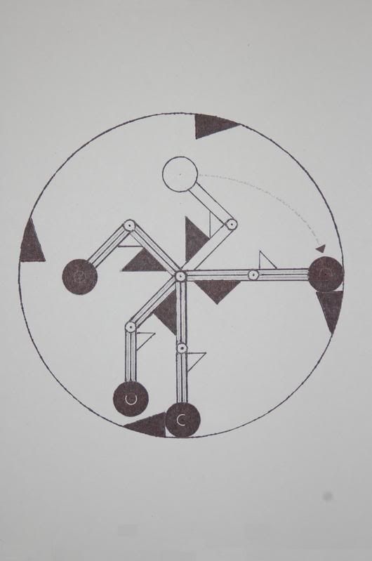
at first glance this wheel may not appear to be out of balance.
look closely at the movement...... use discernment.
.........................................................................................................
key points:
things to notice:
1) weight C hangs freely from the axle when it reaches 6:00.
for the next 1/8 turn (45 degrees) this weight has no influence on rotation.
2) weight U hangs freely from it's 'elbow' (pivot).
weight U applies it's weight to this location --> 'elbow' (pivot).
....................... U C ?
3) arms are independently connected to the axle.
('shoulder' pivots move independantly)
NOT DRAWN:
4) arms are spring-assisted at each joint / pivot.
both the 'shoulder & elbow' are spring-loaded in favor of 'opening' to the position of the 3:00 arm.
5) the finished model is two (above pictured) 4-weight wheels put together.
--> two wheels combined into one 8-weight wheel.
each (4-weight) wheel is offset 1/8 turn (45 degrees) from the other.
wheels are attached (side by side) using the same axle. 8 weights fall during one full rotation.
.................................................................................................
..........................................................................................................................
................
I have not built this model yet.
Last edited by arthur on Tue Sep 18, 2007 4:45 am, edited 4 times in total.
re: arthur's design
Arthur,
well done for trying. You will notice that if you rotate your wheel clockwise even 5 degrees that there are more black weights on the LHS of the wheel, making the LHS heavier hence it will not perpetuate. The impacts will give it a clockwise jolt but this will seem more as a vibration rather than a push to rotate.
Keep trying though. Good to see you are thinking.
I only realized too late that life was short.
re: arthur's design
don't say it will not work unless you have built it.
you're right, there are more weights on the left side of the wheel than the right.
......because the falling weights move faster.
I expect that everyone here will tell me this wheel won't work.
however.... I also expect that this wheel will work.
you're right, there are more weights on the left side of the wheel than the right.
......because the falling weights move faster.
I expect that everyone here will tell me this wheel won't work.
however.... I also expect that this wheel will work.
I have actually built something similar but not exactly the same, but don't let that deter you. By building it it will give you ideas, improvements etc. Most of my ideas have come from building, learning, feeling how a wheel moves when pushed. Some designs just need a small modification to be improved substantially.
-
- Enthusiast
- Posts: 34
- Joined: Wed Jul 18, 2007 9:08 pm
This is very similar to the first design I built, and it balanced. I used four arms 90 degrees apart. Well, I guess it wasn't identical to yours - my arms were fixed at 90 degrees apart from each other. The real problem is the weight at the 9 o'clock position - the weight travels close to the edge of the wheel all the way around the top. Also, if you look closely, the arm at 3 o'clock on your drawing has the dark triangle on the wrong side of the arm! If your arms pivot freely around the axle, what pushes them around (and up) the ascending side? The weights will congregate at the bottom of the wheel and all balance there.
Re: re: arthur's design
Arthur
Build it! if you don't then you will always wonder "what if". As long as it remains in your mind it will impede your innovation leading to tunnel vision. The best laid plans is to see for yourself and then move on with an open mind and consider it a passing grade in PM 101.
Ralph
I have been known to act as a mentor for more than one new member. They claim they have an idea that will surely work. I know it will not, but I do not attempt to convince them. Just the opposite, I assist them with input on how to build.arthur wrote:don't say it will not work unless you have built it.
you're right, there are more weights on the left side of the wheel than the right.
......because the falling weights move faster.
I expect that everyone here will tell me this wheel won't work.
however.... I also expect that this wheel will work.
Build it! if you don't then you will always wonder "what if". As long as it remains in your mind it will impede your innovation leading to tunnel vision. The best laid plans is to see for yourself and then move on with an open mind and consider it a passing grade in PM 101.
Ralph
re: arthur's design
I'm not sure what you're talking about here, GadgetGeek.Also, if you look closely, the arm at 3 o'clock on your drawing has the dark triangle on the wrong side of the arm! If your arms pivot freely around the axle, what pushes them around (and up) the ascending side? The weights will congregate at the bottom of the wheel and all balance there.
the dark triangles represent 'stoppers' fixed to the wheel.
the levers' movement is restricted to a path between these 'stoppers'.
having said that....
this drawing should be rather self-explanatory.
.
Last edited by arthur on Tue Sep 18, 2007 7:37 am, edited 1 time in total.
re: arthur's design
Arthur,
[the dark triangles represent 'stoppers' fixed to the wheel.]
There are five arms shown with four dark triangles and even this statement is false as two are right triangles and two are pyramids.
[The levers' movement is restricted to a path between these 'stoppers'.]
Then why is the one at three on the opposite side of the arm from the others.
[this drawing should be rather self-explanatory.]
Maybe to your eyes as you are the one with the vision that designed it.
GadgetGeek has pointed out the obvious and I have added a little that is apparently not so obvious.
Now I would say quit debating and build as it is clear that you have sold yourself on this concept an no one is going to change your mind. To my thinking that is good. It is time for you to see for yourself.
Look at your drawing and imagine seeing the weights only. draw a vertical plumb line from each weight to the bottom. How many lines are on the left and how many on the right. delete those running through the center axis.
Ralph
re: arthur's design
Ralph,
The dark triangles look right to me. What is confusing is that I think there are only 4 arms. The lighter (unshaded) arm at the top is illustrating where the arm at 3 o'clock starts to fall.
I may be wrong of course.
But this is all academic as it doesn't look as though it will work given that only the 3 o'clock arm is producing torque. The arm at 6 o'clock is valueless by way of torque and there at 2 weights on the ascent (countertorque).
Good design though. Keep on trucking Arthur.
Kas
“We have no right to assume that any physical laws exist, or if they have existed up until now, that they will continue to exist in a similar manner in the future.�
Quote By Max Planck father of Quantum physics 1858 - 1947
re: arthur's design
yes.there are only 4 arms. The lighter (unshaded) arm at the top is illustrating where the arm at 3 o'clock starts to fall.
re: arthur's design
-- a falling weight averages the (clockwise/positive) torque of .925 radius.
(that of a weight falling from 12:00 to 6:00)
-- a rising weight averages negative torque of .85 radius.
radius = distance between axle and center of 3:00 weight.
==== the wheel is not balanced.
(that of a weight falling from 12:00 to 6:00)
-- a rising weight averages negative torque of .85 radius.
radius = distance between axle and center of 3:00 weight.
==== the wheel is not balanced.
re: arthur's design
...also:
as weights fall back, the spring-loaded levers 'close'.
force is stored in springs until weight reaches 12:00.
....weight reaches 12:00 and springs cause levers to swiftly 'open'.
in other words:
----gravity causes weights to close levers, storing energy in springs.
springs are 'loaded' at no cost to torque / rotation.
when weight reaches 12:00 it is propelled forward until it lands with great impact at 3:00.
force of this spring-powered swing was gained from gravity.
this is what I think bessler meant by saying "weights gain force from their own swinging."
re: arthur's design
Don't forget Arthur, Springs produce counter torque too.
If an arm springs at - let say the 11 o'clock position, there will be equal and opposite reaction as described in Newtons 3rd law.
This will use up all the positive torque calculated by weights positions.
Sorry to be the bearer of bad news but I have been where you are many times before.
It has never stopped me from building though . Guess you could say I learn the hard way.
It should never discourage you from continuing with your ingenuity though.
After all, Its what we do.
Kas
“We have no right to assume that any physical laws exist, or if they have existed up until now, that they will continue to exist in a similar manner in the future.�
Quote By Max Planck father of Quantum physics 1858 - 1947
re: arthur's design
....yes, true enough..Don't forget Arthur, Springs produce counter torque too.
If an arm springs at - let say the 11 o'clock position, there will be equal and opposite reaction as described in Newtons 3rd law.
however,
the idea is for the arm to spring froward when the weight reaches 12:00.
the springs will accelerate the weight (downward) all the way to 3:00.
this extra spring force returned at 3:00 impact is greater than the counter-torque.
--for this reason:
I can pick up a rock and throw it at the ground.
==== rock will hit the ground with more force than I used to pick it up and throw it.
-
- Devotee
- Posts: 1718
- Joined: Fri Nov 07, 2003 12:22 pm
- Location: Speyer, Germany
- Contact:
re: arthur's design
Hi Arthur,
in your design you store gravitational energy in the springs on the left side, and release it on the right side.
Hope that your design will work. It looks like a not allowed sign, which is not allowed in Germany since second world war.
the future has begun
Georg
in your design you store gravitational energy in the springs on the left side, and release it on the right side.
Hope that your design will work. It looks like a not allowed sign, which is not allowed in Germany since second world war.
the future has begun
Georg