Morphing Keenie to Bessler
Moderator: scott
Morphing Keenie to Bessler
I've realised that a minimalist Keenie Wheel can be devised which looks very much like the kind of thing Bessler might have built if his drawings are anything to go by.
The figure below shows a beam pivoted at the middle with a pair of weights at each end. The leading arm of a pair is pivoted at the centre so that when its weight reaches 2 o'clock, say, it can be released and fall under gravity. It is as though the weight has been transferred to a very low inertia wheel, zero inertia if we neglect the mass of the arm. Thus it is the boundary case of a Keenie Low Inertia Wheel.
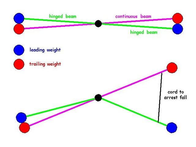
The fall of the hinged half beam is arrested by a cord which transfers the weights kinetic energy to the larger mass of the rest of the beam. Thus we have a situation which is kind of the inverse of Kirk's
"One pound dropped 1 foot launches one 1/4 pound mass 16 feet - their momentum is equivalent.
The ke is 400% dfferent"
except that we are turning KE into rotational momentum rather than the other way around.
Now, it's clear that as far as the vertical gravitational wind is concerned its action is very different on the 12 to 6 side than on the 6 to 12 side.
One could say that on one side KE rules and on the other MOMENTUM rules. We have performed a kind of ju-jitsu on gravity and turned its strength on one side against it on the other.
We can see that the hinged beam resets itself rather conveniently by hanging vertically down until the rest of the beam catches up with it.
The action repeats at 180° with the other hinged half beam and other beams contribute at appropriate angles.
The above argument doesn't pretend to be any proof of anything. It is merely an attempt to set the scene for thinking about how to bias the action of gravity with respect to the two sides of a mechanism.
Who is she that cometh forth as the morning rising, fair as the moon, bright as the sun, terribilis ut castrorum acies ordinata?
re: Morphing Keenie to Bessler
Hi, Frank
A few suppositions on my part; red and blue weights are of equal mass, all four beam segments are equal length, axle (black dot) turns clockwise.
In order for the descending hinged beam to fall ahead of fixed beam, the fixed beam's weight must rotate at a speed less than as driven by gravity. The ascending weights will rotate at the same less than swift speed. Until...
From the time the descending hinged beam 'disconnects' from the axle until it reaches the end of it's rope, the ascending side outweighs the descending side 2:1. The ascending beams should come to a screeching halt and probably start to descend. The 'free' weight won't reach the 4:00 position.
I don't get it. I guess I need more information.
envision, describe, simplify, construct, refine -- repeat any, as necessary
Good point. I suppose it depends how much of a tug the falling weight gives the rest.
But anyway, the concept has given me the insight to solve the KiiKing problem. In view of your thread on the momentum topic which seems to be well on the way there perhaps I shall call it the Kirk Kiik solution.
And, yes, your suppositions are correct.
More later.
But anyway, the concept has given me the insight to solve the KiiKing problem. In view of your thread on the momentum topic which seems to be well on the way there perhaps I shall call it the Kirk Kiik solution.
And, yes, your suppositions are correct.
More later.
re: Morphing Keenie to Bessler
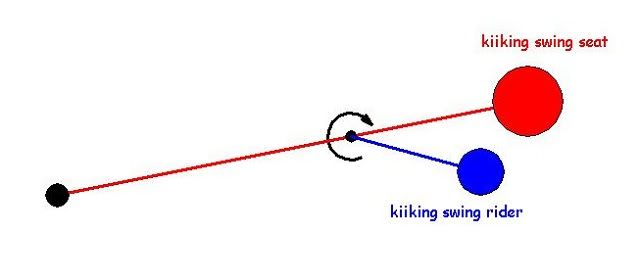
The above diagram shows a Kiiking swing with a blue rider and a red seat. The rider is allowed to fall under gravity at about red 2.30 o'clock, say
The rider falls to blue 4 o'clock. At that point it is arrested by a blue pivot stop. This gives a clockwise jerk couple to the Kiiking swing. Reset is automatic as in the previous Bessler example.
The beauty of using a Kiiking swing is that a 360° pendulum exhibits an adiabatic exchange between Newtonian gravity and Ersatz gravity which means that if the pivot friction and air resistance is very small the pendulum will turn from 12 noon to virtually 12 midnight. Its coefficient of restitution will be nearly 1.00. Consequently, only a very small kick is needed to send the pendulum over the top and into continuous rotation.
Because air resistance increases with speed the swing will eventually reach an equilibrium rpm.
The amount of energy generated by this device is not important. Its relevance lies in the point of principle it demonstrates. Once it is shown that gravity can be harnessed on a continuous basis the rest is simply engineering.
Who is she that cometh forth as the morning rising, fair as the moon, bright as the sun, terribilis ut castrorum acies ordinata?
re: Morphing Keenie to Bessler
Many will easily get to 10, 10.30 or even past 11 o'cl with good bearings.
Frictions reduce the full restitution.
N.B.1. a heavier pendulum will swing higher than a light pendulum - this is because the percentage of air drag losses is proportionally less for a heavy pendulum - same principle as explaining terminal velocity in free fall.
N.B.2. attaching a drive mass along the pendulum shaft close to the axle/pivot will increase the pendulum velocity at 6 o'cl - therefore a drive mass on your 'blue kicker kiiking' shaft might also make it fall faster IMO.
Thanks for all that info Fletch. I'll have to work out what past 11 means in terms of CoE.
I think I can just about manage the trig involved.
The great thing about couples is that it doesn't matter where they act on a beam, the effect is the same.
When I first though about letting the rider fall under gravity I had the hinge on the wrong side and couldn't understand what was going on. Morphing the Keenie wheel led me in the right direction. I suppose one could see the Kiiking swing as a further morphing of the Bessler to the ultimate minimalist solution.
Let's see then.
11 o'clock is 30° off the vertical so
coefficient of restitution = 0.5 + (0.5(cos30)) = 0.93
Mmm... so one would need quite a good kick to get it over the top then.
Of course, if one went about things scientifically one wouldn't need to get it over the top, merely to show that the angle reached with the rider tripped was greater than that reached with the rider locked.
Measure the standard deviation of the CoR for a large number of measurements for each condition, show that the average was higher at some appropriate level of significance and you have proved the principle.
From there you just alter the variables systematically by small increments to find the top of the multidimensional variable hill.
re: Morphing Keenie to Bessler
As you say you don't need a pendulum to swing thru 360 degree [over the top as we say] - you could start it at 3 o'cl having measured its CoM & this its Pe1 - see how high the parts reach on the ascending side before reversing direction - take a photo etc & calculate the combined CoM on that side & figure the Pe2.
If Pe2 > Pe1 you have the basis for a PM/OU machine - if Pe2 < Pe1 & you feel the difference is due to losses you'd have to work on reducing the losses until you could do no better, using current technology - if after that Pe2 was still less than Pe1 then there is something wrong with the theory.
Myself I prefer the full rotation mode because I don't have to dick about with combined CoM's etc - its clear - it restores Pe or not & if it can restore Pe by going over the top then it will also have residual velocity & Ke it didn't have at the stationary start - a clear & simple proof of usable Ke that could be bled off to do Work.
Once you have refined your mechanism it would be quite easy for any one of us to model in WM - there you can set to watch the system CoM/CoG, which automatically sums the parts & their positions & you can quickly see Pe's thru a cycle - some don't trust the software but its real value is in comparing to a real physical build & looking for the differences.
re: Morphing Keenie to Bessler
Grimer,
most of your ideas are hermetic to my understanding. Sorry!
Best!
M.
most of your ideas are hermetic to my understanding. Sorry!
Best!
M.
Last edited by murilo on Wed May 04, 2011 9:15 pm, edited 1 time in total.
re: Morphing Keenie to Bessler
I didn't really understand you second point but it did spark off an idea for generating a couple as the KiiK goes up as well as it goes down.Fletcher wrote:Many will easily get to 10, 10.30 or even past 11 o'cl with good bearings.
Frictions reduce the full restitution.
N.B.1. a heavier pendulum will swing higher than a light pendulum - this is because the percentage of air drag losses is proportionally less for a heavy pendulum - same principle as explaining terminal velocity in free fall.
N.B.2. attaching a drive mass along the pendulum shaft close to the axle/pivot will increase the pendulum velocity at 6 o'cl - therefore a drive mass on your 'blue kicker kiiking' shaft might also make it fall faster IMO.
I have realised for a long time that if I can simulate the kind of reversal that takes place in the Carnot cycle then I am home and dry. However, all my solutions have been one sided. I never seem to be able to get at the other two legs of the cycle, to simulate the kind of commutator reversal that takes place in a simple electric motor, for example.
However, thanks to the stimulation you have provided by your posts, plus the fact that initially I had the kiiking rider falling the wrong way and opposing the rotation rather than assisting the rotation, I can now see my way to a solution.
I'll have to prepare some diagrams to make everything crystal clear.
Anyway, thanks very much for your contributions to this thread. It's encouraged me to think harder.
Who is she that cometh forth as the morning rising, fair as the moon, bright as the sun, terribilis ut castrorum acies ordinata?
Re: re: Morphing Keenie to Bessler
Better hermetic than emetic, eh!murilo wrote:Grimer,
most of your ideas are hermetic to my understanding. Sorry!
...
Who is she that cometh forth as the morning rising, fair as the moon, bright as the sun, terribilis ut castrorum acies ordinata?
re: Morphing Keenie to Bessler
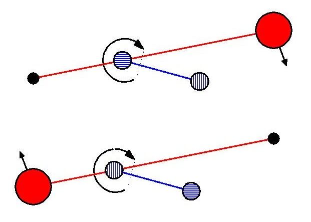
I have taken advantage of the fact that it doesn't matter where the rider is placed to locate him in the middle of the swing.
You will see that the rider has weights at both ends, the blue pivot end and the blue falling end.
Commutation is achieved by switching the pivot at the 12 and 6 o'clock positions from one end to the other. This leads to gravity pulse acting clockwise on both the 12 to 6 and 6 to 12 sides.
Neat, eh!
Switching the pivot ends undoubtedly requires some mechanical ingenuity but it needn't require significant energy.
Whether it will work or not is difficult to say. Depends on the superiority of the third derivative I suppose. But it certainly adds another weapon to the PM armoury and mirrors the Carnot pattern of actions.
Who is she that cometh forth as the morning rising, fair as the moon, bright as the sun, terribilis ut castrorum acies ordinata?
re: Morphing Keenie to Bessler
You've lost me Grimer.
The black dot is the pendulum pivot - the red mass rotates around the CoR.
In your pic the blue pivot position along the pendulum rod appears to have moved to greater radius ?
At some point the dumbell rider swaps ends [hatching in the circles indicate swapping positions, possibly by sliding shaft].
The rider is arrested by a pin stop because you have dispensed with the rope connection ?
What are the projected masses & lengths etc ?
Have you considered the effects of CF on the rider deploying correctly ? - it will want to align with the pendulum rod if its at too greater radius, this it would be greatly effected - better to have it close to the axle.
Sorry if my post was a bit obscure but it's probably easier to answer peoples' queries cos one never knows how much people understand.Fletcher wrote:You've lost me Grimer.
The black dot is the pendulum pivot - the red mass rotates around the CoR.
In your pic the blue pivot position along the pendulum rod appears to have moved to greater radius ?
At some point the dumbbell rider swaps ends [hatching in the circles indicate swapping positions, possibly by sliding shaft].
The rider is arrested by a pin stop because you have dispensed with the rope connection ?
What are the projected masses & lengths etc ?
Have you considered the effects of CF on the rider deploying correctly ? - it will want to align with the pendulum rod if its at too greater radius, this it would be greatly effected - better to have it close to the axle.
The black dot is where the Kiiking swing attaches to the frame - the pivot of the major pendulum in other words.
You are correct about a pinstop at the pivot. The string was just an aid to visualisation.
I moved the blue pivot so that the minor pendulum was in the middle so that the kick going down and the kick going up would be similar in magnitude. (Edit: but I can now see that they will be wherever the blue pivot is situated.)
A 6 and 12 the dumbbell pivot swaps ends. The pivot is withdrawn at one end and pushed in at the other. At this stage I am not concerned how this is achieved mechanically.
As for masses and lengths, I am not bothering about these until I am convinced there isn't a fatal flaw - which there may well be.
I had thought about the effect of CF and seen it as a problem when the thing is in motion. I much like your suggestion that it should be near the main pivot. As I pointed out, the couple generated is the same irrespective of where along the beam the gravity drop takes place.