.....can be more "digestible" for our understanding and easy to test,if reduce the MT13 design "redundancy" (more than is needed).
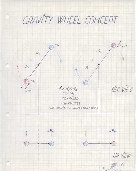
So,a wheel with 12 hinged spokes,becomes a "minimal" wheel with 2 opposite spokes,only...a simple first degree lever,if you like.
If we play two equal masses,at the end of the spokes,than we need:
-a fixed ,median(L) arm
-a variable (L1<L<L2) arm
This arrangement can play a full free 360*("self") rotation,if the hinged end is free to rotate 180*(so,more than 90*...)...and the single "critical point" problem remains in the top position:the "jump" of the variable arm from L1 to L2.
For this "vault" we can imagine a lot of solutions...
All the best! / Alex
MT13 digest...
Moderator: scott
-
iacob alex
- Addict

- Posts: 2448
- Joined: Mon Nov 20, 2006 1:37 am
- Location: costa mesa /CA/US
- Contact:
re: MT13 digest...
Simplicity is the first step to knowledge.
-
iacob alex
- Addict
- Posts: 2448
- Joined: Mon Nov 20, 2006 1:37 am
- Location: costa mesa /CA/US
- Contact:
re: MT13 digest...
.....face to an "ideal" PM image/design can be seen as it follows,if we take a short look at www.orffyre.com/mt1-20.html :
-0* to 180* (long arm)...it's ok
-180* to 270* (short arm )...it's ok
-270* to 360* (short arm it's ok,if the hinged part remains "free" )
We must think about the top point,where we need a "sudden change" of short arm into long arm...this is the only one "missing know how".
To simplify a problem is to start an "icon" ,to open a new window for mind and soul.
Every new opinion,at its starting,is in a minority of one...floating in the extened space and time of majorities.
All the best! / Alex
Simplicity is the first step to knowledge.
-
iacob alex
- Addict
- Posts: 2448
- Joined: Mon Nov 20, 2006 1:37 am
- Location: costa mesa /CA/US
- Contact:
re: MT13 digest...
.....is to play a simplified design ( two opposite arms , only...).
A manifest proof of the non working wheel concept , at :
https://m.youtube.com/watch?v=vxmMovwMXv0
Maybe , MT 13 "digest" is a "hope" for the best...
Al_ex
A manifest proof of the non working wheel concept , at :
https://m.youtube.com/watch?v=vxmMovwMXv0
Maybe , MT 13 "digest" is a "hope" for the best...
Al_ex
Simplicity is the first step to knowledge.
-
iacob alex
- Addict
- Posts: 2448
- Joined: Mon Nov 20, 2006 1:37 am
- Location: costa mesa /CA/US
- Contact:
re: MT13 digest...
.....as proposed up here , is easily : the well known Bessler's MT13 design , with a simple cut down , or playing two opposite spokes/arms only...
The tested non-workability of the many spokes/arms MT13 , at :
https://youtu.be/SA7noI8sHL8
A possible workability , if we remove all the spokes/arms excepting two opposite , only...a simple question of redundance...?!
Al_ex
The tested non-workability of the many spokes/arms MT13 , at :
https://youtu.be/SA7noI8sHL8
A possible workability , if we remove all the spokes/arms excepting two opposite , only...a simple question of redundance...?!
Al_ex
Simplicity is the first step to knowledge.
-
Georg Künstler
- Devotee

- Posts: 1747
- Joined: Fri Nov 07, 2003 12:22 pm
- Location: Speyer, Germany
- Contact:
re: MT13 digest...
Hi Jacob Alex,
an animation created from Claus Enterlein some years ago you can find under
http://www.kuenstler-energie.de/index.php?id=17
You can play the animation in repeat mode to study the movement.
It is none of Bessler's running solutions, neither the one directional not the bi directional wheel. Therefore you need 2 systems.
But we can learn from this.
Gravity can be used to lift and in addition to shift weights in once, to reach the permanent movement.
Best regards
Georg
Georg
-
iacob alex
- Addict
- Posts: 2448
- Joined: Mon Nov 20, 2006 1:37 am
- Location: costa mesa /CA/US
- Contact:
re: MT13 digest...
Hi Georg !
This topic has an old starting point ( 06/30/09 ) , the well known MT13 :
www.orffyre.com/mt1-20.html
...but the proposal is a cut down ( if we play two opposite spokes,only).
So, it's easy to test a "minimal" wheel ( first Class lever ) , with a single variable arm , as follows :
www.geocities.ws/iacob_alex/Some_Drafts/text028.JPG
Al_ex
Simplicity is the first step to knowledge.
-
nebollinger
- Enthusiast

- Posts: 60
- Joined: Tue Sep 06, 2011 7:38 pm
re: MT13 digest...
This drawing got me thinking and..
www.geocities.ws/iacob_alex/Some_Drafts/text028.JPG
I present this as something that might help others in some way.
The problem is how do you push the weight up? Well there is a way
to do that by using 2 weights so that one goes up and the other goes
down but usually that accomplished little or just leads to another problem
so I came up with this.
The following is based on my 2 pulley idea and
this drawing combined
www.geocities.ws/iacob_alex/Some_Drafts/text028.JPG
triangled pulley
1. 3 equal weights, 1 fixed, 2 move oppositly up/dn
making equal weight balanced
2. two weights mounted on three triangled pulleys offset from center
3. 2 makes a weight shift to left and right also
4. weight 2 is toward the axle of rotation
5. weight 3 is the same distance from the axle as fixed weight 1
6. 1,2,3,4,5 enable the set the set to unbalanced and reset to balanced
with very little work in.
Imagine the vertical center line through the axle.
When weight 2 is on that line then and weight 3 is
the same distance from the axle as fixed weight 1 the wheel is balanced
And when weight 2 goes up and to the right at an angle while weight 3 goes
down and to the right at the same angle then they shift to the right causing
a wheel unbalance to the right and thus rotation.
I drew this out and manually rotated it to look for a problem.
And then I rotated the pdf 90 and the 90 more and imagined where the
weights B and C would be.
It will be bottom heavy when it rotates past 120 degrees.
Do you see a problem with this idea?
Perhaps it could be shifted back before 180 degrees.
see my attached drawing.
Perhaps a better arrangement would be drawing II below. Two arrangements can shift the mass either right or left and then rotate 90 degrees and then be reset easily.
Norman
www.geocities.ws/iacob_alex/Some_Drafts/text028.JPG
I present this as something that might help others in some way.
The problem is how do you push the weight up? Well there is a way
to do that by using 2 weights so that one goes up and the other goes
down but usually that accomplished little or just leads to another problem
so I came up with this.
The following is based on my 2 pulley idea and
this drawing combined
www.geocities.ws/iacob_alex/Some_Drafts/text028.JPG
triangled pulley
1. 3 equal weights, 1 fixed, 2 move oppositly up/dn
making equal weight balanced
2. two weights mounted on three triangled pulleys offset from center
3. 2 makes a weight shift to left and right also
4. weight 2 is toward the axle of rotation
5. weight 3 is the same distance from the axle as fixed weight 1
6. 1,2,3,4,5 enable the set the set to unbalanced and reset to balanced
with very little work in.
Imagine the vertical center line through the axle.
When weight 2 is on that line then and weight 3 is
the same distance from the axle as fixed weight 1 the wheel is balanced
And when weight 2 goes up and to the right at an angle while weight 3 goes
down and to the right at the same angle then they shift to the right causing
a wheel unbalance to the right and thus rotation.
I drew this out and manually rotated it to look for a problem.
And then I rotated the pdf 90 and the 90 more and imagined where the
weights B and C would be.
It will be bottom heavy when it rotates past 120 degrees.
Do you see a problem with this idea?
Perhaps it could be shifted back before 180 degrees.
see my attached drawing.
Perhaps a better arrangement would be drawing II below. Two arrangements can shift the mass either right or left and then rotate 90 degrees and then be reset easily.
Norman
- Attachments
-
- triangled.pulleys.pdf
- (15.45 KiB) Downloaded 92 times
-
-
nebollinger
- Enthusiast
- Posts: 60
- Joined: Tue Sep 06, 2011 7:38 pm
re: MT13 digest...
Here is drawing II.
Perhaps a better arrangement would be drawing II below. Two arrangements can shift the mass either right or left and then rotate 90 degrees and then be reset easily.
The triangle represents the weight movement on the pulleys and rope.
There is no switching contained in the idea. Just the very easy balanced weight shifting. I leave that to another day.
I can imagine if this had large weights it could lift a very heavy object for a very small effort ie small work in and larger work out.
Norman
- Attachments
-
-
nebollinger
- Enthusiast
- Posts: 60
- Joined: Tue Sep 06, 2011 7:38 pm
re: MT13 digest...
My further testing shows that neither of the above ideas will work.
They fail to reset easily after rotation.
But the basic idea of something going up and simultaneously down
to make that effort small may still be of some value to you all.
Norman
They fail to reset easily after rotation.
But the basic idea of something going up and simultaneously down
to make that effort small may still be of some value to you all.
Norman
-
iacob alex
- Addict
- Posts: 2448
- Joined: Mon Nov 20, 2006 1:37 am
- Location: costa mesa /CA/US
- Contact:
re: MT13 digest...
Simplicity is the first step to knowledge.
-
iacob alex
- Addict
- Posts: 2448
- Joined: Mon Nov 20, 2006 1:37 am
- Location: costa mesa /CA/US
- Contact:
Re: MT13 digest...
…..with an experiment of a minimized design ( a lever with a single variable arm/free oscillatory pendular mass ) , at :
https://youtu.be/MPNm0Ed83j4?si=tip4aqLKqAKzd4I2
https://youtu.be/MPNm0Ed83j4?si=laAlgZPteKBOaxvi
…..and a single “difference” at : www.geocities.ws/iacob_alex/Some_Drafts/text048.jpg
Al_ex
https://youtu.be/MPNm0Ed83j4?si=tip4aqLKqAKzd4I2
https://youtu.be/MPNm0Ed83j4?si=laAlgZPteKBOaxvi
…..and a single “difference” at : www.geocities.ws/iacob_alex/Some_Drafts/text048.jpg
Al_ex
Last edited by iacob alex on Tue Sep 24, 2024 10:05 pm, edited 1 time in total.
Simplicity is the first step to knowledge.