Why is the L-shaped weight the solution ?
The L-shaped weight distributes the force on two points
1. the force on the sub-axle
2. the force on the rim of the hole
Depending on the weight distribution of the l-shaped weight the roller on the rim in the hole will roll upwards to the 4 o'clock position.
So in my experiment the center of mass is shifted to the right.
This is the elemetary function.
Fletcher was so kind to simulate this elementary function in a circus wheel.
So he used this elementary function twice in the circus wheel and received a torque, until the circus wheel received the 12 o'clock position.
When you look at his sim, you see that the rolling weights are orientated to one direction, one is rolling to the center, the other to the rim of the carrier wheel/circus wheel.
They act simultaneously and syncronized.
In the clock of Praque, we have 12 holes and figures.
So repeat the circus wheel with 4,6,8, N*2 holes.
the gravitational energy converter
Moderator: scott
-
Georg Künstler
- Devotee

- Posts: 1748
- Joined: Fri Nov 07, 2003 12:22 pm
- Location: Speyer, Germany
- Contact:
Re: the gravitational energy converter
Best regards
Georg
Georg
Re: the gravitational energy converter
Mornin Georg ..Georg Keunstler wrote:... Depending on the weight distribution of the l-shaped weight the roller on the rim in the hole will roll upwards to the 4 o'clock position.
So in my experiment the center of mass is shifted to the right. ...
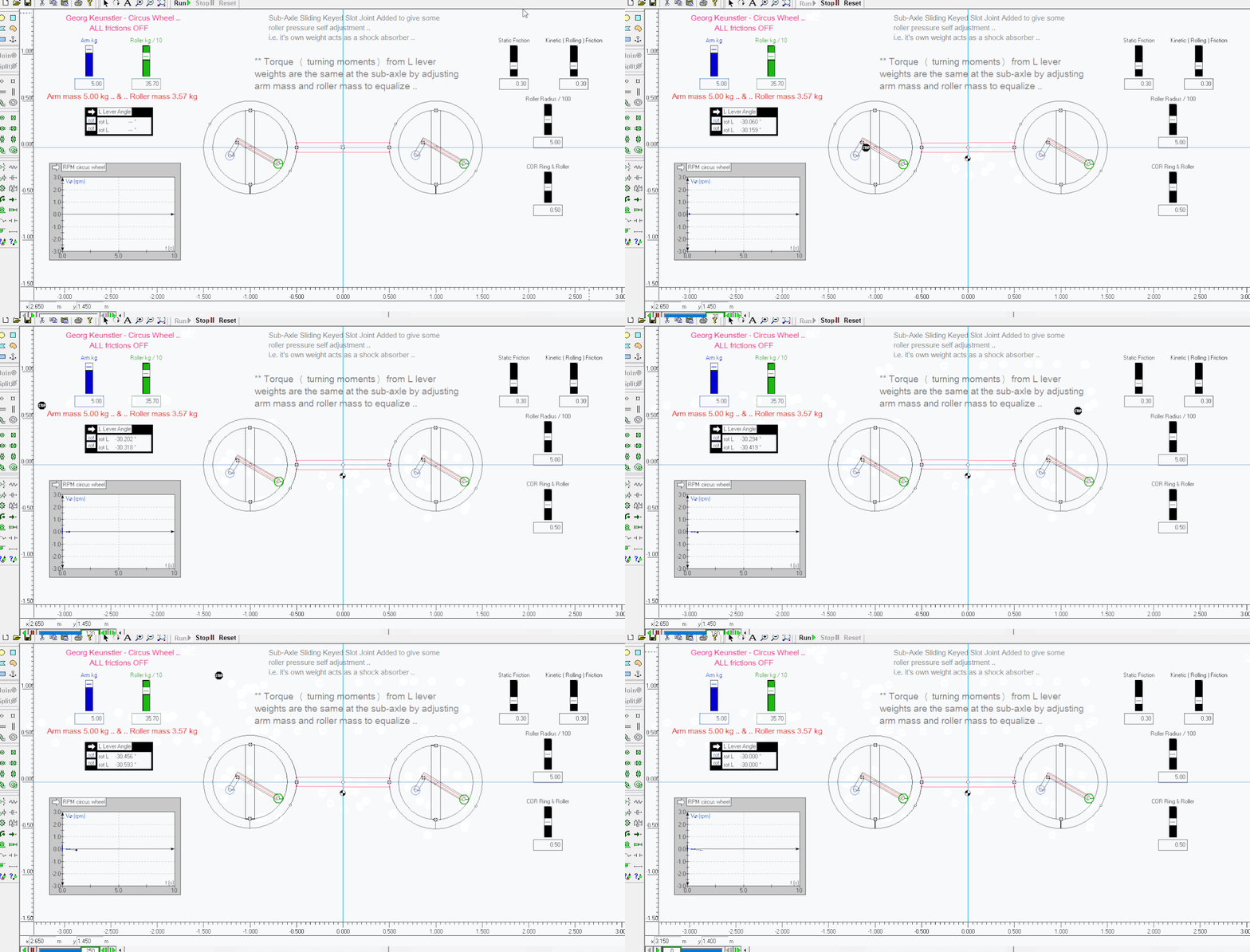
Here is the same circus wheel but this time I adjusted the L lever arm mass and the roller mass to equalize the turning moments ( torque ) at the sub-axle pivot ( 5.00 kg arm mass and 3.57 kg roller mass ) - now the L lever has a tendency to roll on the rim and seek and stay at the 4 o'cl position, if released from either above or below 4 o'cl ..
Result .. the sim is basically stationary as it has no torque - this is what Shadow's original sim showed when turning moments are balanced out .. in my previous sims there was a slight bias ( 5.00 kg each ) which caused the whole wheel to rotate until balance was found ..
.................

.................
-
Georg Künstler
- Devotee

- Posts: 1748
- Joined: Fri Nov 07, 2003 12:22 pm
- Location: Speyer, Germany
- Contact:
Re: the gravitational energy converter
Hi Fletcher,
I concentrated the focus on the cylindrical rollers.
This are the weights in the 4 o'clock position.
I have drawn only them now as a weight in the sketch and you will see that the distance to the main axle is different.
L1 is not equal to L2.
I concentrated the focus on the cylindrical rollers.
This are the weights in the 4 o'clock position.
I have drawn only them now as a weight in the sketch and you will see that the distance to the main axle is different.
L1 is not equal to L2.
Best regards
Georg
Georg
-
Sam Peppiatt
- Devotee

- Posts: 1864
- Joined: Tue Dec 01, 2015 4:12 pm
Re: the gravitational energy converter
Georg,
You have the right idea. The ring and roller never gets bottom heavy. It can provide continuous torque to the wheel and is instantly reversible. However; the roller has to shift continuously. I don't see how oscillations will ever work but, maybe if you can find a better way to do it, you would have a runner-------------------------Sam
You have the right idea. The ring and roller never gets bottom heavy. It can provide continuous torque to the wheel and is instantly reversible. However; the roller has to shift continuously. I don't see how oscillations will ever work but, maybe if you can find a better way to do it, you would have a runner-------------------------Sam
Re: the gravitational energy converter
Hi Georg .. for the L Lever to prefer to stay orientated at the 4 o'cl position then some things have to happen - we know the horizontal distance to both the arm weights and the roller weights to the sub-axle is different - therefore we have to adjust the mass of the arm weight and the roller weight until the L lever is completely balanced ( at the sub-axle ) at the 4 o'cl position ( only the 4 o'cl position ) - IOW's the Turning Moments about the sub-axle are equal ( at 4 o'cl ) i.e. and there is no torque ..Georg Keunstler wrote:
Hi Fletcher,
I concentrated the focus on the cylindrical rollers.
This are the weights in the 4 o'clock position.
I have drawn different length of leverarms.png only them now as a weight in the sketch and you will see that the distance to the main axle is different.
L1 is not equal to L2.
If there are equal turning moments ( no torque / balanced ) at the 4 o'cl position, and the sub-axles are opposite each other at the same radius then they are also balanced ( have no torque ) ..
The result is a perfectly balanced circus-wheel ..
If you change the mass so the turning moments are not equal then you will create a torque bias and the L lever won't come to rest at 4 o'cl but somewhere else where it will be balanced about the sub-axle ..
Balanced Turning Moments ( TMs ) => f1 x d2 = f2 x d1 = 0
Try calculating the TMs at 3 o'cl and 5 o'cl ..
Best ..
...................
Re: the gravitational energy converter
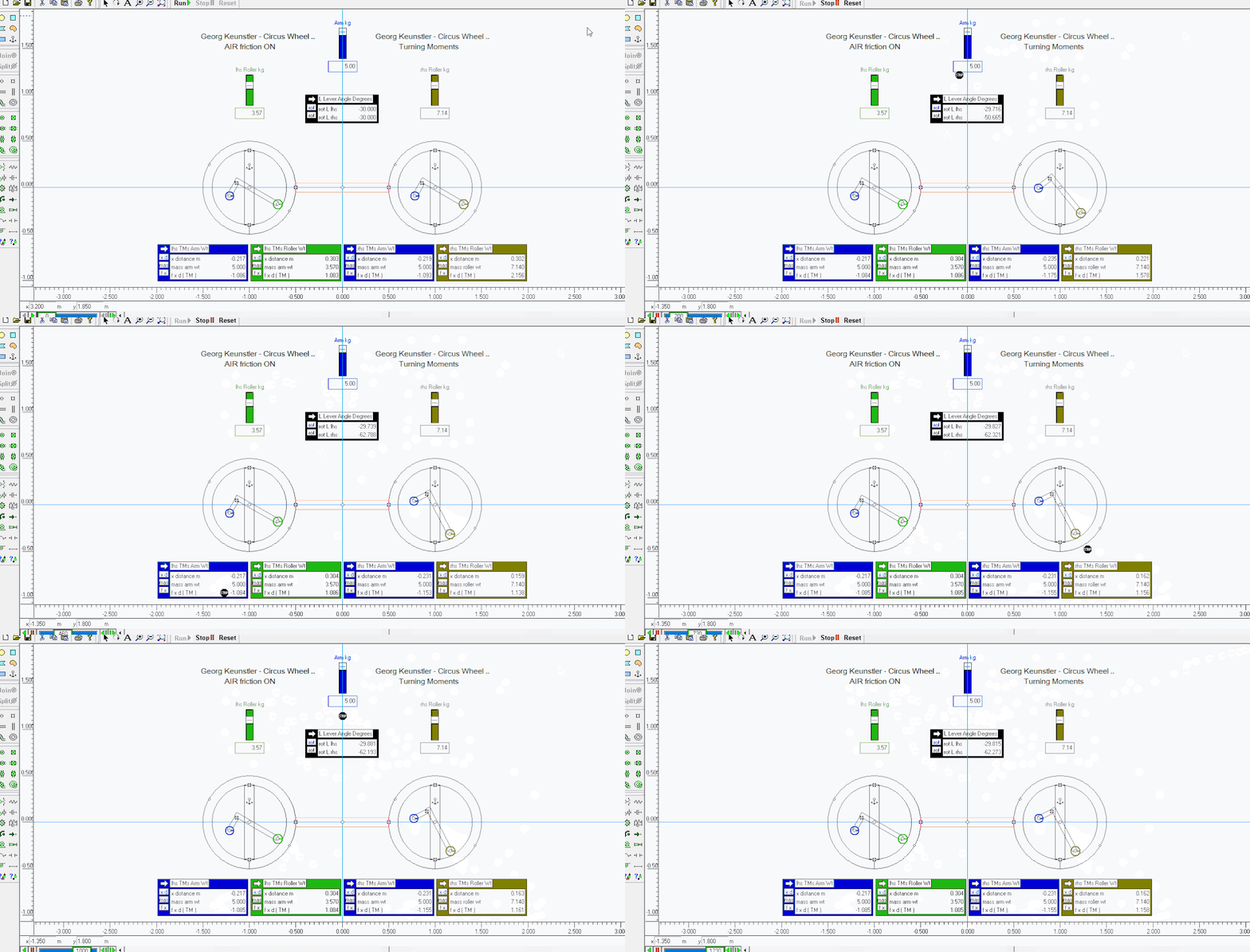
Georg .. here is the TMs calculated when the rhs roller weight is double the lhs roller weight ..
I doubled the roller weight on the right hand side compared to the left hand side roller weight - see the rhs L lever move down to near 5 o'cl and stay there - then each pair TMs are equal each side of the sub-axles at those positions ..
.....................

.....................
I doubled the roller weight on the right hand side compared to the left hand side roller weight - see the rhs L lever move down to near 5 o'cl and stay there - then each pair TMs are equal each side of the sub-axles at those positions ..
.....................

.....................
Last edited by Fletcher on Fri Jan 24, 2025 5:06 am, edited 1 time in total.
-
Georg Künstler
- Devotee

- Posts: 1748
- Joined: Fri Nov 07, 2003 12:22 pm
- Location: Speyer, Germany
- Contact:
Re: the gravitational energy converter
So I see it as confirmed that we get the cylindrical rollers always to the 4 o'clock position.
The 4 o'clock position is achieved only with gravity force.
One weight is arranging the other.
In one hole we have therefore an asymmetric force. The gravity force is shifted vertical.
How much it is shifted vertical is depending on our model size.
A hole is representing an endless lever. With 2 holes I had drawn before we get 2 different length of levers.
A short lever on the left side of the circus wheel and a long lever on the right side of the circus wheel.
The result is that we have now a permanent torque on the circus wheel.
2 holes are enough to show the principle, but 2*n will be better.
I have choosen 8 holes in my construction.
Best regards
Georg
Georg
-
Georg Künstler
- Devotee

- Posts: 1748
- Joined: Fri Nov 07, 2003 12:22 pm
- Location: Speyer, Germany
- Contact:
Re: the gravitational energy converter
Here I messure the force on the surface when we change the angle.
Full force of the weights we have in the vertical position, when the cylinder is at 6 o'clock.
The force is less when we increase the angle, when we roll the cylinder to the 4 o`clock position.
I have prepared also the videos of the messurement under @GeorgKuenstler3108 in youtube.
Full force of the weights we have in the vertical position, when the cylinder is at 6 o'clock.
The force is less when we increase the angle, when we roll the cylinder to the 4 o`clock position.
I have prepared also the videos of the messurement under @GeorgKuenstler3108 in youtube.
Best regards
Georg
Georg
