Meet the Clockmaker: Cracking Bessler's Code

A Bessler, gravity, free-energy free-for-all. Registered users can upload files, conduct polls, and more...

Moderator: scott

User avatar
Novus
Dabbler
Dabbler
Posts: 12
Joined: Fri Mar 03, 2006 3:17 am

Meet the Clockmaker: Cracking Bessler's Code

Post by Novus »

I only just discovered Bessler a few days ago but I believe I have cracked his code and discovered what was inside his wheel.

In order to crack Bessler's code I had to think like him and solve problems the way he would solve them. In many ways I had to become Bessler. In this thread I will attempt to resurrect Bessler's mind and his wheel.

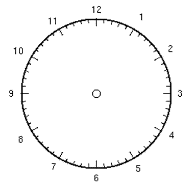
The first and greatest clue to cracking Bessler's code is to look at his background. Bessler was a clockmaker by trade so naturally he saw his wheel as a clock. His wheel was built like a clock.
Image

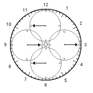
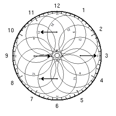
The directions in the boards in his drawing almost hint at a clocklike mechanism. The Bessler Wheel is actually two clocks: the larger wheel itself and a series of clocks acting as hands on the main clock. The clocks are sycronized to three O'clock and move in such a way as shown in the diagrams below.
Image

Image

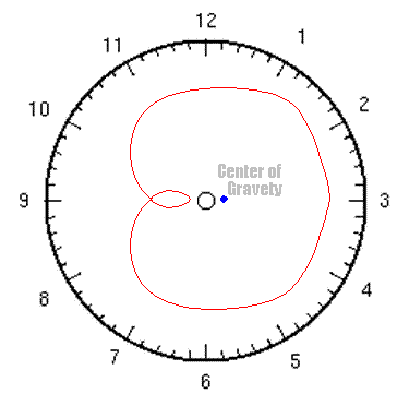
The movement of these clocks creates what is known as a sacred geometry. Sacred geometry is an ancient knowledge with differnt rulesets than Euclidian geometry. Sacred Geometry allows for over unity leavers and various squared circles. Sacred Geometry has had a role in everything from alchemy to building the pyrmids and can even be found in the structures of living organisms and the perpetual rotation of the planets. It is unknown if Bessler independently discovered sacred geometry or read about it in surviving alchemical texts of the period.
Image

Image

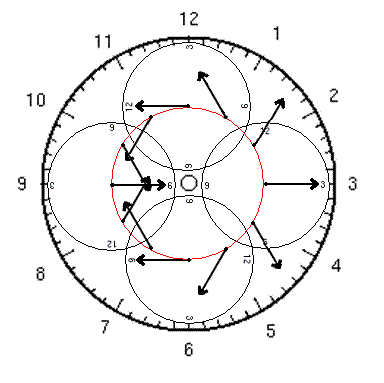
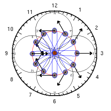
On the tip of each arrow would be a heavy weight. Using this geometry the weights are moved up the center of the wheel where they have little mechanical advantage. While going down the weights would travel down the wheel's edge where they have exponentually greater mechanical advantage. This wheel if built this way would have a perpetual off center gravity which would cause it to rotate and rotate indefinately. The continual movement of the machinery keeps the wheel pretetually off balance as the wheel turns. The power of this wheel is exponentialy proportional to its diameter. Longer diameters bring the weights closer to the center axis while rising and at the same time farther from the center while falling.
Image

Implementation of this complex geometry is remarkably simple. A single stationary gear in the center powers all the other weights. As the wheel turns a chain indepentently turns each arrow. Each complete rotation around the center axis will turn the arrows exactly once. These drawings account for 12 weights but Bessler may have used 16 or even 32 which create greater over unity sacred geometries.

So now that I have shown you how Bessler built his wheel the race is on to see who can build this rather simple clockwork first.
User avatar
barksalot
Enthusiast
Enthusiast
Posts: 170
Joined: Fri Aug 12, 2005 8:29 am
Location: marion. indiana

re: Meet the Clockmaker: Cracking Bessler's Code

Post by barksalot »

Nice presentation, clear and concise. But I'm not convinced this how bessler did it.
User avatar
ken_behrendt
Addict
Addict
Posts: 3487
Joined: Wed Mar 02, 2005 7:45 am
Location: new jersey, usa
Contact:

re: Meet the Clockmaker: Cracking Bessler's Code

Post by ken_behrendt »

Novus...

Thanks for the nice graphics of your design for Bessler's secret wheel mechanism. Well, although its interesting, I do not know if I would use the word "simple" to describe it. It looks like it would require that central overriding (I assume) cog on the wheel's axle to have a lot of chains in contact with it and we have some evidence from Bessler's writings that there was nothing located on his wheel's central axle. Supposedly, he allowed witnesses to reach inside of the drum and "grope" the axle with their hands. That would have been kind of hard to do if he had all of those chains around the axle.

I made a quick analysis of your last diagram and it looks to me like the weights on the right or descending side of the wheel drop the exact same distance that they rise on the left or ascending side. So, there is no difference in the change in gravitational potential energy there that could propel the wheel.

Yet, an analysis of the position of the CG of the weights does, indeed, show it to be to the right of the axle. So, just based on this, one would think that it should turn.

However, I have seen designs like this in the past and none of them worked. The problem was that, as the weights began to move, sudden and unanticipated counter torques would immediately arise that would then block the rotation. I think the same thing will happen in your design.

You wrote:
A single stationary gear in the center powers all the other weights. As the wheel turns a chain indepentently turns each arrow.
Most likely, it will be the contact between the chains and that gear that will create the counter torque that will prevent this design from working.

I would love to do a WM2D model of the design, but it would be a complex one that required much use of the gear tool. Well, maybe if I can find the time, I'll take a crack at it...


ken
Attachments
The weights definitely rise and fall through the same distance on both sides of the wheel.
On 7/6/06, I found, in any overbalanced gravity wheel with rotation rate, ω, axle to CG distance d, and CG dip angle φ, the average vertical velocity of its drive weights is downward and given by:

Vaver = -2(√2)πdωcosφ
User avatar
Novus
Dabbler
Dabbler
Posts: 12
Joined: Fri Mar 03, 2006 3:17 am

re: Meet the Clockmaker: Cracking Bessler's Code

Post by Novus »

ken_behrendt,

Yes it is true that points A & B counteract each other. In fact if you draw a line from 9:00 O'clock to 3 O'clock you will get perfect vertical symmetry. However, that is not how this wheel gets its power from. As Bessler said in one account Leverage is applied at right angles to the axis. To see the right angle of applied work you must draw a line from 12 O'clock to 6 O'clock and compair symmetries. The weight's on the 3 O'clock side overpower the force from the the weights on the 9 O'clock side because they are nearer to the center axis. If you notice your points A and B are both to the right of 12 to 6 line. The center of gravety is directly between points A and B or just right of the central axis.
User avatar
SeaWasp
Aficionado
Aficionado
Posts: 452
Joined: Sat Sep 24, 2005 4:28 am
Location: Darwin, Australia
Contact:

re: Meet the Clockmaker: Cracking Bessler's Code

Post by SeaWasp »

Novus.. Hello & welcome to the board!

It's always great to see some fresh ideas being presented!

Spiros.
The limits of the possible can only be defined by going beyond them into the impossible.
Image
AgingYoung
Aficionado
Aficionado
Posts: 761
Joined: Sun Apr 03, 2005 4:44 am
Location: Houston, TX

re: Meet the Clockmaker: Cracking Bessler's Code

Post by AgingYoung »

Novus,

I need to take a better look at your idea but my initial 'shooting from the hip' speculation is that it's an elaborate clock/balance that will instantaneously obey Newton's third law with monotonous regularity.

Gene


Image <-- I'm with stupid
Working Model 2DImage
[It is] the glory of God to conceal a thing: but the honour of kings [is] to search out a matter.
coylo

re: Meet the Clockmaker: Cracking Bessler's Code

Post by coylo »

It's nice to see someone taking the time to make a good presentation. You're diagrams were very good. However, Gene is right.
If you simply take a straight vertical line down the centre through the pivot you'll have 3 weights agianst 7, with 2 more or less neutral - which would balance torque distances you've made in your arrangement.

"A" for effort!
Attachments
inventory99.jpg
coylo

re: Meet the Clockmaker: Cracking Bessler's Code

Post by coylo »

By the way, I've corrected your drawing below.

You illustrated a parallel arrangement, where as what you desire needs the additional gears shown (plus another 8 not shown - gets a little crowded).
Attachments
BesslerMechanical2.jpg
User avatar
ken_behrendt
Addict
Addict
Posts: 3487
Joined: Wed Mar 02, 2005 7:45 am
Location: new jersey, usa
Contact:

re: Meet the Clockmaker: Cracking Bessler's Code

Post by ken_behrendt »

Novus...

I had a couple of minutes to spare and decided to attempt making a WM2D model based on your proposed design. A screenshot of that model's simulation is attached below.

As I suspected, even though the model is overbalanced to the right of the axle, there are CCW torques present that prevent it from moving.

In my model I replaced the chains with gears and rods that would have made each small 2 lb blue weight rotate CW around its yellow support disc's center twice for every single rotation of the large wheel, so I think it simulates what you suggested quite closely. All 12 of the blue weight discs are connected to a single central disc which is not physically attached to the larger wheel, but, rather, is held stationary by the long blue arm that is, itself, attached to the fixed Background

As can be seen by the flat velocity graph for the large wheel in the upper right hand corner, this wheel wouldn't budge at all...


ken
Attachments
Looks interesting...but, does not work.
On 7/6/06, I found, in any overbalanced gravity wheel with rotation rate, &#969;, axle to CG distance d, and CG dip angle &#966;, the average vertical velocity of its drive weights is downward and given by:

Vaver = -2(&#8730;2)&#960;d&#969;cos&#966;
rlortie
Addict
Addict
Posts: 8475
Joined: Thu Jan 06, 2005 6:20 pm
Location: Stanfield Or.

re: Meet the Clockmaker: Cracking Bessler's Code

Post by rlortie »

Gentleman,

I do apologize for not being educated and not having any aptitude for math. Because of this known fact I look at such designs with a physical or empirical view.

I only had to look at the second sketch in the above series to conclude that it will not work. Why! because all the weighted levers are pinned to the same equal radius the circumference of the wheel. Sticking a weighted lever out one way or the other does not change the transference of the weight. Oh! how many times this point has been mentioned.

Sorry but I see no need for WM2D, calculator or sacred geometry.

Ralph
AgingYoung
Aficionado
Aficionado
Posts: 761
Joined: Sun Apr 03, 2005 4:44 am
Location: Houston, TX

re: Meet the Clockmaker: Cracking Bessler's Code

Post by AgingYoung »

I'm going to go out on a limb :). I think Novus was yanking our sacred ungeometric chains.

Gene
Working Model 2DImage
[It is] the glory of God to conceal a thing: but the honour of kings [is] to search out a matter.
User avatar
rks1878
Aficionado
Aficionado
Posts: 470
Joined: Sun May 08, 2005 5:40 pm
Location: On Horseback

re: Meet the Clockmaker: Cracking Bessler's Code

Post by rks1878 »

Novus,
You would benefit from tring to build.
You would see that anything that touches the main wheel and is "held" there, even dynamic, BECOMES A LEVER.

ROBERT
Robert (The Carpenter's Boy)

There's never time to do it right the first time, but there's always time to do it over again.
AgingYoung
Aficionado
Aficionado
Posts: 761
Joined: Sun Apr 03, 2005 4:44 am
Location: Houston, TX

re: Meet the Clockmaker: Cracking Bessler's Code

Post by AgingYoung »

clue number one:
I only just discovered Bessler a few days ago but I believe I have cracked his code and discovered what was inside his wheel.
There are more tips laying around than Jacob's sons left because of Shechem.

Gene

ps edit: Novus (Last Visit: Mon Mar 06, 2006 6:50 am)
ps edit²: Novus (Last Visit: Mon Mar 06, 2006 12:50 pm) checking in at lunch I guess.
ps edit&#179;: Novus (Last Visit: Mon Mar 06, 2006 5:00 pm) lurking?
Last edited by AgingYoung on Mon Mar 06, 2006 11:52 pm, edited 1 time in total.
Working Model 2DImage
[It is] the glory of God to conceal a thing: but the honour of kings [is] to search out a matter.
User avatar
ken_behrendt
Addict
Addict
Posts: 3487
Joined: Wed Mar 02, 2005 7:45 am
Location: new jersey, usa
Contact:

re: Meet the Clockmaker: Cracking Bessler's Code

Post by ken_behrendt »

Well, I think the major problem with Novus' wheel is that its weights must make physical contact with a gear on stationary gear surrounding its internal axle. This allows for the creation of the counter torques that prevent any motion from taking place.

And, of course, this configuration violates two of the 12 LAWS of Mechanical Perpetual Motion that I suggested may have been what Bessler had in mind when he made reference to these in DT:
2.) No part of the imbalance maintenance system must remain stationary on the wheel's axle

3.) No part of the imbalance maintenance system must contact any fixed structures external to the wheel.
In the WM2D model I made, it is obvious how the 12 shifting weights are in contact with an "external" structure which was the yellow circle held at the center of the wheel by the long blue arm that was attached to the Background outside of the model.


ken
On 7/6/06, I found, in any overbalanced gravity wheel with rotation rate, &#969;, axle to CG distance d, and CG dip angle &#966;, the average vertical velocity of its drive weights is downward and given by:

Vaver = -2(&#8730;2)&#960;d&#969;cos&#966;
User avatar
Patrick
Aficionado
Aficionado
Posts: 443
Joined: Tue Nov 04, 2003 10:40 pm
Location: Toronto

re: Meet the Clockmaker: Cracking Bessler's Code

Post by Patrick »

Hi Novus;
I like this idea you have presented, very straightforward and easy to understand. Just curious; your design has four main inner wheels/clocks. Have you made any designs with just three?
--Patrick
Post Reply