MTM5

A Bessler, gravity, free-energy free-for-all. Registered users can upload files, conduct polls, and more...

Moderator: scott

Post Reply
MrVibrating
Addict
Addict
Posts: 2879
Joined: Sat Jul 31, 2010 12:19 am
Location: W3

MTM5

Post by MrVibrating »

Starting a new thread as the last one was hijacked by children.

This evening i modelled the revision i mentioned in my last post of that thread - now kiiking by controlled application of counter-torques from accelerating then decelerating an angular inertia, rather than by applying the ice-skater effect; the result is the same, of decelerating the drop phase whist accelerating the lifting phase relative to gravity's constant acceleration, thus garnering a consistent per-cycle momentum gain from gravity and time, but no longer reliant on an input workload that squares with RPM as CF-PE does, instead the only workload now being accelerating and decelerating angular inertia.

In the current crude application, a heavy flywheel is attached to the main wheel at fixed radius, thus overbalancing it and causing it to keel under gravity, and this is mounted via a motor. The motor is then controlled for 'velocity' using the following instruction:

Code: Select all

 "if(body[5].p.x<0,body[1].v.r,-body[1].v.r)" 
- where body5 is the flywheel and body1 the main wheel

In other words, if the flywheel's on the left side of the 0,0 origin at the wheel's axis - thus descending - then the motor turns the flywheel in the same direction and at the same speed as the wheel itself. The resulting counter-torques from this acceleration slow down the drop, prolonging the OB weight's exposure time to gravity's constant acceleration, and so increasing the momentum yield available from the given weight and height.

Passing BDC onto the right side of the axis, the torque sign is reversed and the flywheel spins down, thus unloading its stored momentum back into the wheel axis and so accelerating the lift, reducing its dwell time under gravity's constant deceleration, and so reducing the amount of gained angular momentum that must be shed back to gravity and time, consolidating this boosted per-cycle momentum yield over a succession of five full cycles.

The ratio of KE gain to work performed by the motor is then measured by two different metrics - power x time and force x displacement - at sufficient accuracy to resolve the interaction down to millijoule noise levels. In principle, anyway - the last attempt, MTM4, exhibited a rare failure to resolve consistently, hence this further development of the core idea; the possibility that CF force may offer a proxy for accessing RPM-invariant momentum gains from gravity and time.

The problem this is trying to address is the fact that all else being equal, drop times and thus G*t yields decrease inversely to RPM - the faster the wheel turns, the less momentum is gained from each identical lift and drop of the OB cycle. So your GPE never changes, but the amount of fresh angular momentum it's worth each cycle is decreasing inversely to the square of RPM - at 10X the speed the OB weight spends one-tenth the time under gravity's constant acceleration.

CF force however also squares with RPM, hence at 10x the speed we'd have access to 100x the effective g-force. Surely this could help redress the dwindling momentum returns as RPM's rise?

..and i know what you're thinking; if the CF force is squaring with RPM then wouldn't the cost of momentum also? No! Because we're not performing work against CF force, strictly speaking; we're not even performing work against gravity: the only workload, again, being accelerating and decelerating angular inertia. This seems an eminently conservative exchange - for instance if we accelerate the flywheel by 1 rad/s relative to the main wheel, and then decelerate it back to relative stasis, then almost the same amount of work has been output as input - it's virtually the same torque times angle in each direction, minus the small per-cycle KE gain.

The motivating principle here is simply the fact that it costs ½ J to accelerate 1 kg-m² by 1 rad/s from a standing-start, regardless of the absolute system RPM; doesn't matter if the wheel's stationary or else already turning at 10 rad/s, half a joule of work will produce a 1 rad/s relative speed difference between the 1 kg-m² flywheel and main wheel. This is obviously conducive to the objective of RPM-invariant momentum costs.

So with these points in mind, here's a first draft of what this interaction currently looks like:

Image

Note that the net displacement between the two parts remains zero; the flywheel's effectively oscillating, but precisely because the relative speed isn't increasing, neither is the input workload or its associated energy cost.

The reason why everything in a true PMM must, of necessity, go around together - the EMGAT principle - is that the energy cost of momentum sourced from pushing against a stator inevitably squares with the squaring distance over which that force must be applied in order to continue accelerating, this being the practical factor enforcing PE:KE symmetry. Thus the benefit of a stator you can take with you is in preventing that cost from escalating; again, a 1 rad/s relative acceleration of 1 kg-m² always costs half a Joule from relative stasis, no matter the current system angular velocity.

The torque over angle plot is obviously immediately interesting in this respect - each cycle tracing the identical T*a - ie. performing the same, unchanging workload - invariant of the accumulating system RPM's..

Bear in mind that the intention was to mount such a system inside a larger wheel, replacing real gravity with centrifugal force; the thinking being, that as CF force squares with RPM, this will be equivalent to gravity increasing with RPM, thus potentially cancelling out the usual diminishing momentum returns with rising RPM's, whilst fixing the unit-energy cost of those momentum gains to a constant per-cycle value. OU would then develop as the difference between the final KE value versus the sum of the per-cycle cost times the number of elapsed cycles. I still intend to try this.

But something else has come up.. something unexpected: that rig you see above, the one temporarily using gravity? Yup. Consistently. Always positive, never negative.

The first run made 32 J, with the input metrics coming out like this:

P*t = 23.62619071
T*a = 23.62614435

Sub-millijoule agreement there. I reduced the initial small kick of energy given to it to cause it to topple over in the right direction to a negligible amount, and lowered the integration error to 1e-20 with variable integration steps, managing to get the KE rise for the same five cycles down to 27.45 J (as in the sim seen above), for this cost:

P*t = 24.21164033
T*a = 24.21162772

..again, sub-millijoule agreement, apparently showing a PE discount far above noise levels (four sigma?).

The interaction's simple enough anyone can model it themselves - deploy counter momenta to slow down the drop and speed up the lift, aiming for zero net relative displacement between the two parts, and measure its efficiency over rising RPM..

I'm gonna plough ahead and mount one of these under G-force instead of real gravity - i expect i'll use a motor to turn the system and produce the CF force initially, rather than an OB system; all i really need to know for now is how efficiency evolves as a function of rising G-force, ie. does this compensate the usual diminishing dp/dt returns of increasing angular velocity, and if so how does its cost sum over successive cycles and rising RPM? But even at this early stage, the principal appears to be gaining energy under ordinary gravitation..

Anyone out there yet to indulge the joys of cutting and pasting 32k lines of data into a spreadsheet Riemann sum, today is your day; this needs independently verifying ASAP..
Attachments
MTM5.wm2d
(9.61 KiB) Downloaded 298 times
Last edited by MrVibrating on Mon Nov 27, 2023 3:56 am, edited 3 times in total.
MrVibrating
Addict
Addict
Posts: 2879
Joined: Sat Jul 31, 2010 12:19 am
Location: W3

Re: MTM5

Post by MrVibrating »

Here's the interaction translated into a rotating frame, with gravity disabled and substituted by around 1G of CF force:

Image
Taken at 1e-20 integrator error (ie. took longer to run than set up)


Results:

Primed KE: 23.0587500013500350
Final KE: 47.9390680934626660
KE rise: 24.880318092112631
Kiiking P*t: 19.74185521
Kiiking T*dØ: 19.74184883
Wheel P*t: -55.29963143
Wheel T*dØ: -55.29963143

Pretty astonishing huh? The KE gain (PE discount) is still there - about 5 J - but you can give that to the dogs; there's a bleedin' 55 J PE gain on the wheel motor!

The wheel motor is regulating the wheel speed to a constant 2 rad/s, to maintain semi-consistent internal forces; we could vary the speed dynamically to exert a constant 1G of force on the weight even as it changes radius from the wheel's center, however this would introduce angular accelerations that would interfere with the kiiking action. Obviously my intention was to see how efficiency evolves with rising speed and G-forces, but i was just holding it at 2 rad/s for now in order to compare CoP's with the gravitating version to see if the same gain margin appears - which it evidently does - what i hadn't forseen however was that the energy gain on the kiiker is already feeding back into the system, by subsidising the work required to pull the wheel's MoI back in..

In other words, the wheel's MoI is varying as the weight on the kiiking rotor changes radius relative to the wheel body, and this is incurring the ice-skater effect - attempting to slow the wheel down as the weight approaches the rim, and speed it back up as it rotates back inward again - with these inertial accelerations and decelerations instead being countered by the wheel motor, maintaining that steady 2 rad/s. In short, the wheel motor is performing less work in accelerating the system against the widening MoI, than the system itself is performing against the motor when being decelerated by it against the retracting MoI.

The wheel motor is essentially harvesting gain from braking the wheel against its inertial acceleration from the ice-skater effect!

And this PE gain is 11x the KE gain!

Totting it all up, we gained:

5.138462882112631 J KE + 55.29963143 J PE = 60.438094312112631 J

..with 4-sigma on the KE gain and 8-sigma on the PE gain.

19.74185521 J in for 60.438094312112631 J out (O/I) gives a CoP of 3.06, or 306 % of unity.

Not one, but two different free energy gradients in the same simple system of 3 moving parts..

Sim's enclosed, using the same settings the above results are from - feel free to loosen up the precision if you just wanna see it running. I didn't quite max out the frequency - couldn't wait another three hours for it to run again..

Lots to digest here, but if these results are sound then the bigger prize is obviously that PE gain on the wheel motor rather than the PE discount on the kiiking motor..
Attachments
MTM5.1.wm2d
(19.1 KiB) Downloaded 276 times
User avatar
Fletcher
Addict
Addict
Posts: 8508
Joined: Wed Nov 05, 2003 9:03 am
Location: NZ

Re: MTM5

Post by Fletcher »

Hi MrV .. I know you have put a lot of work and thought into your current approach with actuators and motors, changing MOI, etc, over the last few years .. let me say here and now I'm no electrician .. so take what I say with a grain of salt and it's not meant as criticism ..

Background .. back in time I did a lot of sim work with pendulums and particularly their bobs - letting them free-wheel and at bdc locking them etc (or the other way around) (using position activated pin-joints or rods etc) - the idea was to approximate a latch system to lock or unlock the bob while swinging - and to gauge the effect it had on the system MOI etc .. there were no free lunches in sim-sorld with mechanical approximations of latching and unlatching at specific times i.e. no growth in GPE or KE (unlike your sims) ..

Back to your sims .. because I am no electrician or electrical physicist I would probably question the validity of the energy readings for your motors ..

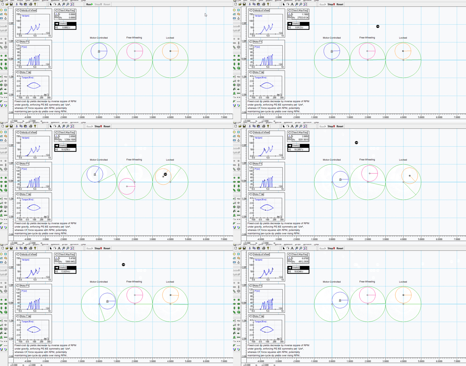
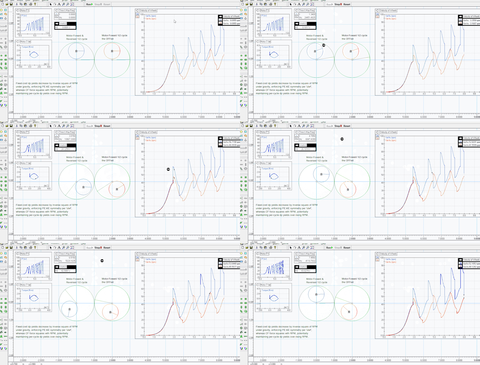
Here are doctored sims of yours where I do comparisons i.e. the first is just to show the basic MOI relationships and the second where the motor is stopped at bdc i.e. the motor is NOT reversed ..

** My thoughts are these when looking at the comparison analysis - you could run side-by-side sims .. 1. full forward and backward mode 2. forward half cycle 3. backward half cycle .. then compare motor energy requirements for each and do they trend and align ?

N.B. note in the sim that both wheels altho identical do not cross bdc at the same time - and watch for the spike in RPM when the motor is reversed n.b. fwiw I think this is like cruising down the highway and slamming your automatic into reverse - the car still travels forward and slows before reversing, if you still have tyres .. in the sim it just slams into reverse and I believe this is unrealistic and causes the major 30% spike upwards in RPM, IINM ..

Ultimately you may need to build or have built a real-world equivalent system and do actual energy measurements etc to prove a real gain in manipulating MOI this way imo ..

...........

Image

...........

Image

...........

Sims attached ..
Attachments
MTM5-FT1a.wm2d
(15.99 KiB) Downloaded 248 times
MTM5-FT1b.wm2d
(16.04 KiB) Downloaded 267 times
MrVibrating
Addict
Addict
Posts: 2879
Joined: Sat Jul 31, 2010 12:19 am
Location: W3

Re: MTM5

Post by MrVibrating »

A further astonishing conclusion that may be considered is that, under real gravity as opposed to CF force, there is no cost involved in maintaining its constant acceleration.. gravity's entirely passive in that respect.

Yet in order to harness the same gain principle under artificial gravity / G-force, work must be done in order to regulate the force acceleration constant.

I had obviously anticipated this; however the expectation was that, if the net load on the wheel motor wasn't a zero-sum, it'd likely be negative, in direct proportion to the KE gain and so balancing the books; basically half-expecting to find that the gain was only tenable under real gravity, with the CF-variant remaining a closed system.

And yet this current gain is produced without gravity even enabled! The momentum source / sink is not G*t, but simply the background / static FoR, or whatever the wheel motor's attached to.

It's just an inertial interaction; not a gravitational one!
User avatar
Fletcher
Addict
Addict
Posts: 8508
Joined: Wed Nov 05, 2003 9:03 am
Location: NZ

Re: MTM5

Post by Fletcher »

Because gravity is conservative then it must be an inertial interaction that outputs the extra KE/Work capability .. gravity force is the enabler in a B. wheel imo ..
MrVibrating
Addict
Addict
Posts: 2879
Joined: Sat Jul 31, 2010 12:19 am
Location: W3

Re: MTM5

Post by MrVibrating »

@Fletch thanks for looking in mate.

- the inverse cycle inverts the sign of the ±F*t asymmetry, shedding more momentum back to the g-force than is gained from it, hence the kiiking rotor - which is free-wheeling after the brief priming phase - would never complete a full cycle in reverse from a near-standing start like this; with a faster push-start it would decelerate each cycle until keeling

I agree WRT to breaking down the runs into shorter single-cycles or even single-strokes for independent analysis and corroboration. I'll get around to all of this in time; right now i've been blind-sided by this unexpected - and much larger - PE gain on the wheel motor.. understanding and optimising this is obvs a priority, not least with the 8-sigma cross-check (and that's how many digits Excel outputs; all data was taken at 16 digits).

And yes the hard reverse on the kiiking motor can be eliminated -the motor control code was only intended as a crude first draft to get the thing kiiking in the first place; progressive accelerations are always preferable. However it's merely an inertial interaction which conserves momentum; the rotor doesn't actually reverse, only stopping to dump its momentum back into the wheel which then rotates back around it for zero net displacement. I'm not sure it is unrealistic, since the kiiking axis is open and free-wheeling, and angular momentum is always conserved in angular inertial interactions in WM. CoE is, obvioushly, contingent upon CoM, so i don't currently see any red lights or potential error sources. I've intended to refine the motor control code in time, however, so we'll see what effect gentler accelerations have on the gain margins..

The drop-speed difference between the three examples you synced is a function of their respective inertias; the motor controlled one is obviously intentionally kiiking (ie. plying an up vs down F*t asymmetry) so falls slowest because it has the most amount of mass undergoing the most acceleration, the free-wheeling one is fastest because it doesn't have to spin up the angular inertia of the internal rotor, whereas the locked one does, making it second-slowest. These are the redux principles of kiiking you're demonstrating!

But the 5 J PE discount is now eclipsed by this extra 55 J somehow harnessed out of nowhere by the wheel motor! Where the hell did that come from?
MrVibrating
Addict
Addict
Posts: 2879
Joined: Sat Jul 31, 2010 12:19 am
Location: W3

Re: MTM5

Post by MrVibrating »

Fletcher wrote: Mon Nov 27, 2023 10:34 pm Because gravity is conservative then it must be an inertial interaction that outputs the extra KE/Work capability .. gravity force is the enabler in a B. wheel imo ..
I'm knocked for six on this tho, honestly; my thinking seemed axiomatic - closed-system inertial interactions were the problem, actively enforcing PE:KE symmetry, whereas force * time asymmetries were the prospective solution, the way out of that tail-chasing loop, the only other means of raising momentum in an otherwise-closed system! The EMGAT principle! My entire focus over the last 5+ years..


Yet gravity's disabled in this sim! I've been conceptually snookering myself all this time!

But it looks like you're right; it's basically not the source of momentum that matters, so much as what is done with it.. how it's divided up and recombined once in the system..
MrVibrating
Addict
Addict
Posts: 2879
Joined: Sat Jul 31, 2010 12:19 am
Location: W3

Re: MTM5

Post by MrVibrating »

So the gain sequence for this 55 J seems to involve employing kiiking as a means of assisting an MoI retraction, with the gain manifesting as the resulting positive inertial torque? Basically an input-energy discount on the cost of accelerating via the ice-skater principal?

Need to identify exactly where the and why the magic's occurring.

It's obviously nothing to do with electronics or motors per se - in WM they're basically pin joints that can be controlled for angle, velocity, torque or acceleration, without further regard; "power" in the P*t meter is simply force times velocity, ie. entirely Newtonian, as is the F*t work-energy equivalence principle. There's nothing intrinsic to the interaction that isn't or can't be done purely mechanically.

The simple fact that the input work integral appears justifiably and demonstrably RPM-invariant - tracing the same force * displacement plot each cycle, even as kiiking speed and momentum accumulate - ought not to be overlooked; what i need to establish is whether this is indeed fixing not just the cost of the work done, but also the per-cycle momentum gain it accomplishes, otherwise speed-invariant per-cycle costs are useless in and of themselves if the momentum yield's still dropping off with higher RPM's. If this is effectively fixing the unit-energy cost of momentum to an RPM-invariant value, then the gain must be equal to the difference between the absolute KE minus the sum of the fixed-cost momenta times the number of elapsed cycles.

Basically if it is genuine OU then it'll all be fully accountable and attributable to empirical, measurable principals and actions.. the gain principles just need reducing, refining and then fully auditing..
User avatar
Fletcher
Addict
Addict
Posts: 8508
Joined: Wed Nov 05, 2003 9:03 am
Location: NZ

Re: MTM5

Post by Fletcher »

And, if a B. wheel Outputs Work/Energy (f x d) in Joules, and gravity is just a force (conservative at that i.e. returns no more GPE than it received aka passive as you described it) in Newtons, and EMGAT - then that very same Output of Work/Energy Equivalence must be manifested by way of a real and physical mechanical "Interaction/Input" with a Large Momentum Sink willing to shed some of its momentum/RKE to the B. wheel to transform into Work Output as well as accelerate and regenerate GPE cyclically, in a gravity environment .. imo ..
MrVibrating
Addict
Addict
Posts: 2879
Joined: Sat Jul 31, 2010 12:19 am
Location: W3

Re: MTM5

Post by MrVibrating »

Just going back to first principles, if you have a black box that's OU and all it contains is purely-mechanical inertial interactions and gravitational interactions, then the only way out of the 'something for nothing' paradox (the "1+1=3?" impasse) lies in disentangling the vis viva resolution, and the introduction of this notion of a divergent inertial reference frame.

Such a system is dependent upon a momentum asymmetry: either it has or produces an asymmetric distribution of momentum to counter-momentum, or else it has been endowed with a change in momentum without inertial interaction with its environment. The first would imply an effective N3 violation, the second an N1 violation. Because momentum and energy are comprised of the same components only scaling differently, the energy gain is obviously then equal to the half-square of the 'velocity' component of the anomalous momentum delta, this providing the divergent inertial frame relative to which the internal energy is conserved, even though it now breaks energy equivalence with all other velocity frames.

Thus it may be surmised that whatever is in the black box must be fixing the unit-energy cost of momentum to a speed-invariant value - ie. if the KE and thus momentum gain is disproportionate to the energy cost then we're getting the stuff on the cheap. Which is only to restate that KE is absolute in the objective frame, so OU is only resolvable in terms of an effective PE discount anyway. Inside the black box is a divergent inertial frame.

If the momentum source/sink isn't ephemeral asymmetric force / time interactions with gravity but simply physical inertial interactions, as appears to be the case here (the system is exchanging momentum with Earth via the wheel motor's stator), then the divergence must be due to an asymmetric distribution of momentum and counter-momentum..

It is because of the fact that momentum has polarity, positive or negative, that asymmetric distributions actually alter net system momentum; for example without polarity a 60% : 40% distribution still sums to 100%, whereas a +60% : -40% distribution sums to +20%, hence why an effective N3 violation produces an effective N1 violation (or equally, why sinking counter-momentum outside the system leaves an effective momentum gain).

In short the black box analysis suggests this must be what's happening here.. Momentum's being source from the wheel motor's stator connection to ground, then asymmetrically distributed inside to produce this divergent inertial FoR. Again, the prospective exploit being tested here is fixing the unit-energy cost of momentum by kiiking against CF force, on the understanding that kiiking only conserves net momentum if the system's truly closed / inertially isolated - originally intending to pipe in more momentum via an OB system, but now apparently demonstrating - as you point out - that how that fresh momentum is introduced is almost academic; a motor with stator suffices for restoring wheel angular momentum and thus maintaining CF force..

..ultimately however, momentum is being drawn from that CF force by the kiiking action, which remains an I/O F*t asymmetry progressing under inertial isolation.. and the whole, calculated point of which was to fix the unit-energy cost of accumulating angular momentum independently of wheel speed, wherever it's ultimately sourced from. The momentum divergence / N3 break must be between the internal rotor and wheel body..

I'm gonna use the sim to zoom in on single cycles of the kiiking action, comparing results at various wheel speeds, with a focus on energy cost of momentum; yields / costs * RPM, type stuff. We can already see speed-invariance in the torque * angle plots - angular inertia's speed-invariant just as intended - so it needs to be confirmed that we're also regulating dp/dt yields, or else we're still paying fixed costs for diminishing returns and the exploit must lie elsewhere..

So things seem to be shaping up as intended; the only detail that's really thrown me so far is this monster PE gain on the wheel motor, an order of magnitude over the kiiking PE discount. Whilst processing the wheel motor F*d integral, having just seen the 55 J excess on the P*t integral, i was half-expecting it to come out with some random figure, confirming the false positive.. instead, it bangs out the same ten-digit number.. "do what mate?".. don't mind admitting i didn't expect that..

Still working eves for now so i'll keep chipping away at it when i can; the two first priorities i think should be eliminating sudden accelerations, confirming the disunity remains, but also hi-res analysis of single cycles, already at-speed rather than from teetering starts, just to see if the sudden acceleration is breaking physics, mechanics or computer science.. ie. thus saying something of gain legitimacy.. the soft-accelerations solution i can mull over at work, but equally if anyone else wants to chip in here, the objective principle is simply that eg. a 1 rad/s acceleration applied to a 1 kg-m² wheel at relative stasis has a ½ J cost, invariant of initial RPM, so all we want to do is spin up by that same 1 rad/s when descending, and then de-spin back to relative stasis while rising. Spin-up on the down-stroke, spin-down on the up-stroke. Simples.

A final point, just to kick it out there, was that we could mount the kiiking rotor centrally, coaxially to the wheel as in MTM4, and using radially-sliding weights; the approach i've used instead is a simpler like-for-like substitution of CF force for the gravitating version, but it's not the only way of doing it.. although i'm not sure that'd offer any particular benefit for now.. (two different OU gradients from three moving parts - three discs - all rotating in the same direction seems astonishing in its own right; either this is some kind of gross error, or we're already tapping into something elemental..)
MrVibrating
Addict
Addict
Posts: 2879
Joined: Sat Jul 31, 2010 12:19 am
Location: W3

Re: MTM5

Post by MrVibrating »

Eek - the thought struck me at work, where there was nothing i could do about it at the time, but what if the velocity reversal isn't respecting N3? Then there would be a divergent inertial frame and corresponding energy gain.. only it wouldn't be legitimate!

It was always more likely another false positive. I'm gonna go back to square one, kiiking under gravity, but controlling the motor for torque or acceleration instead of velocity. If that does indeed kill the KE gain / PE discount, then i'll try it again under CF to check if it also kills the larger PE gain on the wheel motor. This whole thing just seems too easy for a legit gain..
User avatar
Fletcher
Addict
Addict
Posts: 8508
Joined: Wed Nov 05, 2003 9:03 am
Location: NZ

Re: MTM5

Post by Fletcher »

Looking forward to your workups MrV ..

For those skimming this thread his last sim above was viewed from the big disk background Frame Of Reference (FOR) - IOW's if viewed in the normal FOR the wheel and kiiking weight would be rotating around a stationary wheel ..

The background wheel (which has inertia) is rotated by a motor, which takes Power/Energy .. the weight wheel and kiiking wheel are also turned by motor, requiring Power/Energy ..

Gravity is turned OFF - but Cf's still exist because inertia is across all F'sOR ..

.............

fwiw .. I previously had problems reliably simulating an earth background interaction with a pure mechanical wheel or mechanism placed on it and influenced by gravity force - that could demonstrate a parasitic momentum exchange from earth to mech etc .. doesn't mean it can't be done but I personally didn't have the patience and time (or probably skill) to find expert dependable workarounds in the sim-world environment .. but this was dealing with a mechanical structure which limited my choices, whereas MrV is investigating a more holistic approach, and good luck to him ..

ETA .. crossed posts ..
Last edited by Fletcher on Tue Nov 28, 2023 11:25 pm, edited 1 time in total.
MrVibrating
Addict
Addict
Posts: 2879
Joined: Sat Jul 31, 2010 12:19 am
Location: W3

Re: MTM5

Post by MrVibrating »

Well, knocked up a rough approximation of my intentions - i took the 'sin' of the main wheel, which produces a number beginning at zero at 12 o' clock TDC, progressing to +1 at 9 o' clock, then back down to zero approaching 6 o' clock BDC, then inverting coming back up the other side; so approaching -1 at 3 o' clock, then smoothly back to zero at TDC. A useful number to use as a multiplier in a variety of ways; i just took the easy option of multiplying it by '2' and using it to control the motor's velocity; assuming it's not controlling for 'velocity' per se that would cause an issue, so much as sudden changes. At least this way, the acceleration's constantly changing and thus, presumably (touch wood) incurring the full compliment of N3 etc.

This is all very rough and ready, but here's the original gravitating version:

Image

..biggest gripe here is that the angle's increasing over consecutive cycles; in principal it should be possible to prevent this, spinning up and down by the same precise angle each cycle for no net change. But no time to fuss; all we wanna know this evening is whether this kills the gain margins or not. At fairly low precision settings, the above run resolved to unity within millijoules; the PE discount / KE gain has disappeared.

But we had not one, but two, different, free energy gradients - the other one only arising in the wheel motor providing the CF when kiiking under G-force.. so let's check THAT one again, eh? Logically, we'll also have lost the same PE discount as here on the kiiking motor, but what about that massive gain on the wheel motor - maybe we're still in with a chance there?

Let's check it out:

Image

..again, this is quick'n'dirty - only 1 kHz, but 1e-16 on the integrator error:

Initial KE = 23.0051
Final KE = 31.3459
KE rise = 8.3408
Kiiking P*t = 8.34450435
Wheel P*t = -14.26410275

..oh my days we are still in the game! Did i not say you can give the little 'un to the dogs, eh? For 8 J in and out we've gained another 14 outa nowhere.

The motor in the first sim's controlled for 'velocity' using this: "2*sin(Body[1].p.r)", and the second one just adjusts the sign and subtracts the rotation of the main wheel: "-2*(sin(body[5].p.r-body[1].p.r))". Simplicity itself.

I intend to refine this closer to the original intentions, using that same sin value as a multiplier for accelerating to and from a specific speed, 1 rad/s or whatevs, to eliminate any angle creep as the interaction cycles.. but even in this rough state we can see that the ice-skater effect - from the blue weight changing radius relative to the large wheel - is performing more work against the central wheel motor, than it is performing in turn against these inertial torques; that difference is accumulating as apparently-free excess energy..!
Last edited by MrVibrating on Wed Nov 29, 2023 12:47 am, edited 1 time in total.
MrVibrating
Addict
Addict
Posts: 2879
Joined: Sat Jul 31, 2010 12:19 am
Location: W3

Re: MTM5

Post by MrVibrating »

Setting up a high-precision run of that last one now, max-freq at 1e-20, see if we can't get another 8-sigma match between the two wheel motor metrics.. Give it a few hours to run, will post results later..
User avatar
Fletcher
Addict
Addict
Posts: 8508
Joined: Wed Nov 05, 2003 9:03 am
Location: NZ

Re: MTM5

Post by Fletcher »

What happens if you build and measure it ALL in SI units (you do now) but rotation is in degrees instead of radians ?

Then the IF - AND - OR - MOD etc formulas are even more simple IINM ..
Last edited by Fletcher on Wed Nov 29, 2023 2:16 am, edited 1 time in total.
Post Reply