Impact is the Key
Moderator: scott
Mmm... That was a very interesting and informative piece.
I liked the idea of "long helical scoops, to give smooth torque". I didn't realise the devices on top of vans were Flettner Ventilators though I had of course often seen the ground level advertising Savonius turbines.
Thanks for digging that out Doc.
I liked the idea of "long helical scoops, to give smooth torque". I didn't realise the devices on top of vans were Flettner Ventilators though I had of course often seen the ground level advertising Savonius turbines.
Thanks for digging that out Doc.
- path_finder
- Addict

- Posts: 2372
- Joined: Wed Dec 10, 2008 9:32 am
- Location: Paris (France)
re: Impact is the Key
some water for the mill...
http://peswiki.com/index.php/Image:US-G ... _1-2-2.JPG
All ingredients of the Bessler saga are included in the design.
http://peswiki.com/index.php/Image:US-G ... _1-2-2.JPG
All ingredients of the Bessler saga are included in the design.
I cannot imagine why nobody though on this before, including myself? It is so simple!...
-
Bill_Mothershead
- Aficionado

- Posts: 329
- Joined: Sat Feb 02, 2008 5:52 pm
- Location: Phoenix, AZ
re: Impact is the Key
concerning the image at:
http://peswiki.com/index.php/Image:US-G ... _1-2-2.JPG
There seems to be a lot of detail in a very small image.
Caption says it is 178 × 258 pixels...I can't quite seem to read
the lettering, titles/captions, etc.
Details on levers and general moving parts are just a blur
when I zoom in.
Anybody [Path_finder] want to speculate on what this is supposed to show?
re: Impact is the Key
Looks like spring loaded arms that get cocked at the bottom as they run over the large wheel and then release at the top.
meChANical Man.
--------------------
"All things move according to the whims of the great magnet"; Hunter S. Thompson.
--------------------
"All things move according to the whims of the great magnet"; Hunter S. Thompson.
re: Impact is the Key
The drawing is by inventor Raj Balkee, Little can be found on it as he is pushing his tidal and wave generator.
You can find more at: http://peswiki.com/index.php/Directory: ... _Generator
He is backed by Royal Dutch Shell.
Also he is mentioned at: http://www.siteselection.com/features/2 ... ve-Energy/
You can find more at: http://peswiki.com/index.php/Directory: ... _Generator
He is backed by Royal Dutch Shell.
Also he is mentioned at: http://www.siteselection.com/features/2 ... ve-Energy/
re: Impact is the Key
Mmm...
I see that it's over a year since this thread died.
Like the daughter of Jairus, it needs to be resurrected.
Thanks to the insights gained from the Conservation of Jerk thread resurrection is now possible. The Conservation of Jerk thread will therefore be continued here.
Executive Summary
Every engineer is taught (or should be) that a weight applied instantly to a beam gives twice the energy than a weight applied slowly. In the limit a beam under instant loading will deflect twice as far as the same beam loaded slowly.
The descent of a weight on a low inertia wheel simulates the fast loading condition.
The ascent of a weight on a high inertia wheel simulates the slow loading condition.
This means that the low inertial wheel rotating down a given distance generates twice the energy needed to raise the high inertia wheel the same distance. Half the energy of the low inertia wheel's descent is therefore available to do useful work.
Diagrams and a more detailed explanation to follow.
Who is she that cometh forth as the morning rising, fair as the moon, bright as the sun, terribilis ut castrorum acies ordinata?
re: Impact is the Key
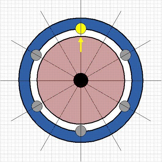
This first figure shows the initial state of the wheels. The grey weights are all on the high inertia blue wheel. The yellow weight and the yellow arrow at 12 o'clock mark the relative progressive rotation.
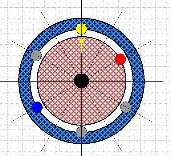
This second figure shows a weight being transferred from the high inertial blue wheel to the low inertia red wheel. The transferred weight is coloured red.
Transfer of this weight from the blue to the red wheel leaves an empty place on the blue wheel. The weight diametrically opposite this this empty place is unbalanced. The unbalanced weight is coloured blue.
Who is she that cometh forth as the morning rising, fair as the moon, bright as the sun, terribilis ut castrorum acies ordinata?
re: Impact is the Key
If the wheels are rigidly connected and the distance between the axles on the wheels is small then the clockwise moment of the red weight will balance the counter-clockwise moment of the blue weight for all practical purposes. This represents the upper boundary of connectivity.
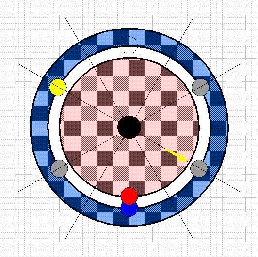
If on the other hand the wheels are completely unconnected then the red weight will keel clockwise and the blue weight keel counter-clockwise to the positions shown above. This represents the lower boundary of connectivity.
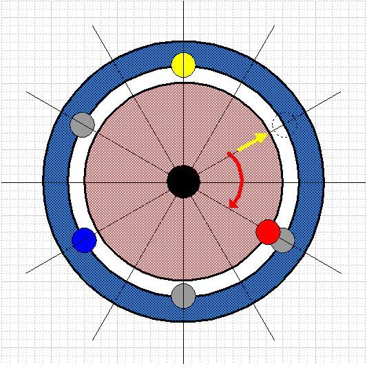
The wheels are then connected with a torsion tube or equivalent device capable of taking up the elastic strain energy of differential movement between the two wheels. The blue wheel is fixed in position and the red weight is allowed to fall from 2 o'clock to 4 o'clock under gravity.
The red weight will first accelerate, reach a maximum speed at 3 o'clock as the gravitational energy is transduced into strain energy and then decelerate until it stops at 4 o'clock. The red weight is provided with a free wheel to prevent it rising back to the equilibrium energy position at 3 o'clock.
Because the inertia of the red wheel tends to zero the energy transduced into strain energy corresponds to the instant loading energy on a beam, i.e. it is twice the slow loading energy.
If the inertia of the red wheel were very high then the red wheel would have a very low acceleration-deceleration profile and only provide half the energy in going from 2'oclock to 4 o'clock as is provided by the high acceleration-deceleration of the red weight.
You can appreciate that the free wheel ratchet mechanism is essential to prevent the red weight moving back to the equilibrium position with loss of the overshoot energy.

If on the other hand the wheels are completely unconnected then the red weight will keel clockwise and the blue weight keel counter-clockwise to the positions shown above. This represents the lower boundary of connectivity.

The wheels are then connected with a torsion tube or equivalent device capable of taking up the elastic strain energy of differential movement between the two wheels. The blue wheel is fixed in position and the red weight is allowed to fall from 2 o'clock to 4 o'clock under gravity.
The red weight will first accelerate, reach a maximum speed at 3 o'clock as the gravitational energy is transduced into strain energy and then decelerate until it stops at 4 o'clock. The red weight is provided with a free wheel to prevent it rising back to the equilibrium energy position at 3 o'clock.
Because the inertia of the red wheel tends to zero the energy transduced into strain energy corresponds to the instant loading energy on a beam, i.e. it is twice the slow loading energy.
If the inertia of the red wheel were very high then the red wheel would have a very low acceleration-deceleration profile and only provide half the energy in going from 2'oclock to 4 o'clock as is provided by the high acceleration-deceleration of the red weight.
You can appreciate that the free wheel ratchet mechanism is essential to prevent the red weight moving back to the equilibrium position with loss of the overshoot energy.
Who is she that cometh forth as the morning rising, fair as the moon, bright as the sun, terribilis ut castrorum acies ordinata?
re: Impact is the Key
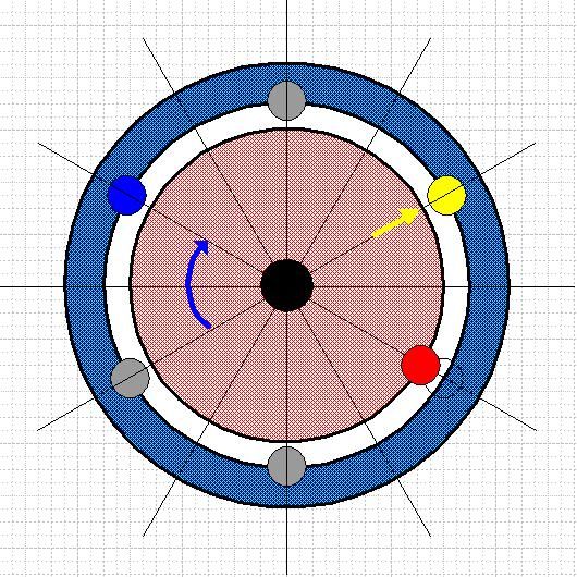
With the red wheel stopped the blue weight can be released and allowed to rise to the reset position as shown above. Because the blue wheel has high inertia the acceleration-deceleration profile is low and only half the strain energy from the torsion tube is required. The other half is available to do useful work, indeed it must be used to do work or else repeated cycles will accelerate the wheel to destruction.
The following quote from Ralph's paper gives the idea of what will happen.
"It was also stated that a number of wooden test wheels were constructed previous to the cast/forged iron model that now exist. One of these test models allegedly over run with acceleration that it flew apart putting a weight through the single board siding of the shed he was working in.
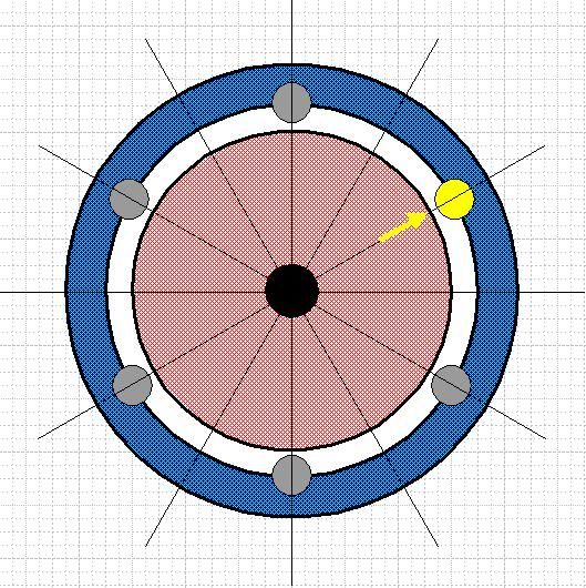
Finally, the red weight is transferred back to the blue wheel ready for the cycle to repeat.
Who is she that cometh forth as the morning rising, fair as the moon, bright as the sun, terribilis ut castrorum acies ordinata?
- path_finder
- Addict

- Posts: 2372
- Joined: Wed Dec 10, 2008 9:32 am
- Location: Paris (France)
re: Impact is the Key
Dear Grimer,
On the principle I totally agree, but I found some minor differences in the timing diagram.
Per example your third drawing above (DISC11g.jpg) describes well the final keeling position, but the previous steps are interesting, in particular:
- the red weight (starting at 2:00) will first lift-up clockwise until about 9:00, then oscillate backward and forward around 6:00 if nothing else happens.
The best action is to lock it to the torsion bar precisely when it reaches 9:00 (without to allow it to go back)
- meanwhile the blue weight will go down, but because the high inertia, with a more slower speed counterclockwise than the red weight, even if with an acceleration.
Therefore it will arrive finally at about 5:30, but much more late after the locking of the red weight. Et that time it must be locked too to the torsion bar.
This motion is complex, but I made the corresponding animation (not sure it is fully certified as valid). I will publish it (with your credit for sure).
I'm in way to review the rest of the motion.
Regarding what you call the 'torsion tube' I made a quick drawing showing how we can imagine this mechanism.
An hollow tube cannot be used for any torsion.
So far the solution is to use a set of N bars (diameter about 20mm) soldered at each end to one of the both wheel like in the drawing.
The number N and the length of the bars depend from the couple developed by the wheel and therefore by its size.
The torsion bars are in red, the tube linked to the outer wheel is in light blue, and the shaft linked to the inner wheel is in rosa.
The difficulty is coming from the maximum angle we want to obtain for the excursion between the two rotational discs.
It is obvious that an assembly like in this drawing cannot support more than 60 grades (30 grades for each direction).
For the more angular excursion the bars cannot be enrolled around the central shaft without a definitive deformation.
Another point to be solved is the clutch (ratchet) which must be associated to this set of torsion bars.
This returns us to the question of the spiral spring, or something which can be equivalent, based on a set of helicoidal standard springs.
There is still remaining a lot of work
I cannot imagine why nobody though on this before, including myself? It is so simple!...
re: Impact is the Key
Thanks for your interesting and constructive contribution, Path_finder.
I accept you arguments absolutely on the practical details. I am only concerned with the theoretical principle on which I am happy to note that you "totally agree". It will be interesting to hear the views of other members. For if the principle is sound then the way to obtain useful work from gravity is rediscovered at last.
I split the various operations up into separate steps since I find it easier to understand the essential details that way and arrive at a view on the soundness or otherwise of the argument.
I leave it to others far more qualified than me to devise practical solutions.
I agree with you about the torsion and that building a robust working model will not be achieved without overcoming considerable practical problems. However the rewards of such an achievement are so great that any capable mechanical engineer sufficiently convinced that the principle is sound should be able to design and construct a successful device.
It will probably be some spotty Gates-like nerd equipped with the latest electronic gizmos and computerized remote control switches who is first to the punch.
Who is she that cometh forth as the morning rising, fair as the moon, bright as the sun, terribilis ut castrorum acies ordinata?
...........................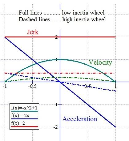
The above graph shows the difference in the three derivatives of position with respect to time for a given weight attached to high and low inertia wheels and acting against a strain energy store.
For a high inertial wheel the acceleration due to gravity is greatly attenuated which lead to lower initial velocity, lower acceleration and lower jerk.
Who is she that cometh forth as the morning rising, fair as the moon, bright as the sun, terribilis ut castrorum acies ordinata?