
This is the math I am basing my work on. It has been rejected based on the fact that I did it. Unfortunately, some people make this a personal issue.
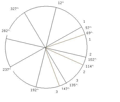
The attached digram shows a wheel with 8 levers rotated clockwise 12 degrees. This refers to having weights at 0 degrees and 180 degrees.
In the diagram, I used ^ to denote degrees and will continue to do so.
The numbers are as follows when worked out.
Under balance over balance
327^ 11.27.................12^ 4.30
282^ 20.08.................69^ 22.32
237^ 16.99...............102^ 21.84
192^ 4.30.................147^ 13.20
------------------.............------------------
..........52.64........................61.63
There is a 12^ advance in levers that is allowed. This is how a weight can be retracted by a value of 3.5. The calculations are based on over balance having a value of 24 while under balance has a value of 20.5.
Positions 1,2 and 3 show the starting position as well as the advanced position of the levers.
The weight at 12^ is not over balanced as it's lever would need to rotate sufficiently to allow the weight to roll out.
See the engineering test model, 1 idea for abetter understanding of this dynamic type of behavior.
It was edited as a result of previewing not showing that the numbers from over balance and under balance would be placed next to each other with no spacing.